How to Plan an Industrial Coating Line? Pre-Quotation Guide

A successful industrial coating line is planned by evaluating product flow, process stages, capacity and factory layout as one complete system—not simply by selecting a booth, oven or conveyor. Choosing equipment before the products, coating system, production targets and existing plant conditions are clearly defined can lead to bottlenecks, energy losses and costly modifications.

For an accurate technical quotation, product dimensions and weights, material and surface condition, hourly and annual capacity, paint and chemical data, quality targets and available utilities should be defined with measurable information wherever possible. These inputs allow the pre-treatment, application, handling, drying, curing, ventilation and automation systems to be sized for the actual production requirement.

This guide explains the technical data, capacity calculations and principal planning steps to prepare before requesting a quotation for liquid paint, powder coating, e-coat (KTL) and similar industrial coating lines. At Elsisan, we evaluate these inputs not only against target capacity, but also in relation to energy consumption, operating cost, process reliability and future growth.

1. Define the Products to Be Coated

Average product dimensions alone are not sufficient when planning a coating line. The complete product family must be evaluated together, with separate attention given to the largest, heaviest, highest-volume and most difficult-to-coat or handle products. This establishes the correct design limits and allows the equipment to be sized for the actual production requirement.

1.1. Minimum and Maximum Product Dimensions

Product width, length and height directly affect the sizing of the pre-treatment system, coating booth, oven, conveyor route and automatic application zones.

Accurate maximum dimensions are particularly important for defining booth and oven openings, safe spacing between products, conveyor curves and required line clearances. If a product may swing or rotate during transport, this movement must also be included in the design envelope.

1.2. Product Weight and Material

Product weight is a primary input for determining conveyor capacity and hanger or fixture design. On suspended lines, the combined load of the product, hanger, fixture and carrier must be considered. Weight data is also essential for planning safe and ergonomic loading and unloading. Where heavy parts are unsuitable for manual handling, suitable lifting and transfer equipment should be evaluated during the project stage. Correct planning reduces operator workload, improves loading and unloading times and supports stable operation at the target capacity.

Product material is an important factor in defining the pre-treatment and coating process. Steel, aluminium, galvanised steel and other materials can require different cleaning, pre-treatment, drying and coating stages. The material and existing surface condition should therefore be clearly identified at the start of the project.

1.3. Surfaces to Be Coated

The existing surface condition is as important as the substrate material. Oil, corrosion, manufacturing residue or any previous coating should be clearly identified and evaluated when defining the pre-treatment and coating process.

Technical drawings should clearly indicate the areas to be coated, left uncoated, protected or masked. Threaded holes, electrical contact points, assembly surfaces and similar details directly affect gun positioning, application access and masking requirements.
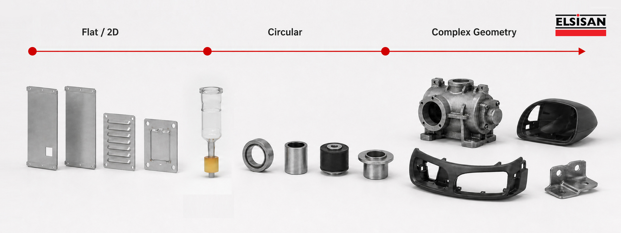
Examples progressing from flat and two-dimensional parts to circular and complex geometries

1.4. Hanging Method

When defining the hanging method, consider the product orientation and direction of travel, suspension points, number of parts per hanger and any need for rotation. The product must remain stable and secure; its centre of gravity, risk of swinging and clearance through booths, ovens and other openings must be reflected in the fixture design.

Marks that may be left by hangers and contact points, and whether those points will remain visible on the finished product, should be evaluated in advance. Where electrical contact is required, its location should be clearly defined in the drawings and hanger design.

If chemical pre-treatment is used, product orientation requires additional consideration. Where the part contains pockets that could retain water or process chemicals, it should be suspended in an orientation that allows liquids to drain freely.
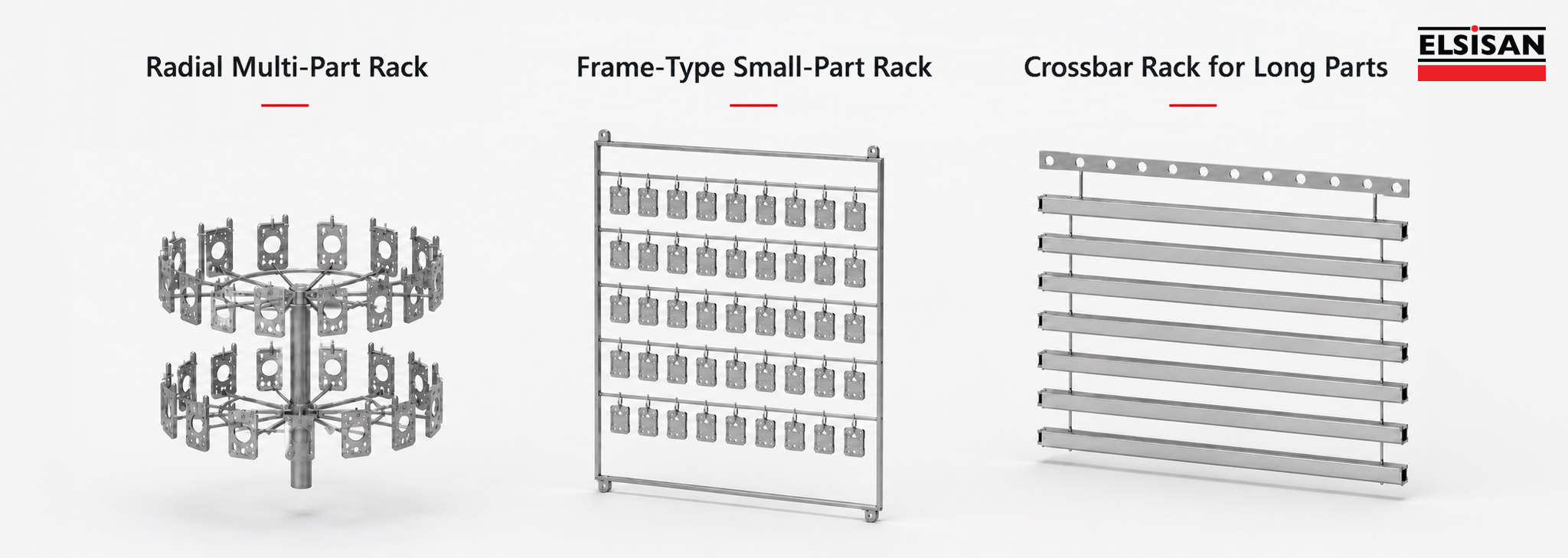
Radial multi-part, frame-type small-part and crossbar racks for long parts

1.5. Preparing a Product Matrix

Instead of evaluating products independently, prepare a product matrix that presents the principal technical data for all product groups together.

The values below are examples only.

Product GroupDimensionsWeightMaterialUnits per Hour
Product A500 × 400 × 300 mm12 kgSteel80
Product B1.200 × 600 × 400 mm35 kgGalvanised Steel25
Product C800 × 500 × 250 mm8 kgAluminium45

The product matrix is used not only to show product diversity, but also to establish the actual design limits of the coating line. Evaluating dimensions, weights, materials and production quantities together makes it easier to determine which product groups should govern the line sizing.

Products with low production volumes but unusually large dimensions or weights should be evaluated separately. Including these parts on the main line can significantly increase booth and oven dimensions, conveyor capacity, line length, energy demand, floor-space requirement and total investment cost.

For example, a plant producing mainly 600 × 400 mm parts may also need to coat a limited number of 3,000 mm products. Sizing the entire system around this exceptional part can create additional capacity with a very low utilisation rate. In such a case, evaluate whether coating that product by a different method outside the main line would be more appropriate technically and economically.

A product matrix helps clarify the following decisions:

  • Which product or product group should govern the line dimensions.
  • Whether low-volume or exceptional parts can be handled outside the main system.
  • Which products have the greatest impact on the investment budget.
  • Whether separating the main production line from special-product solutions is technically and economically appropriate.

The objective is not to include every product in the same system, but to define the correct project scope by considering product dimensions, production volumes, technical requirements and investment economics together. This makes it possible to engineer a line that matches the actual production need instead of an oversized system with substantial unused capacity.

At Elsisan, we evaluate product diversity and production targets together from the start of the project to establish a balanced scope in terms of investment cost, energy consumption and operating efficiency.

2. Determine Production Capacity

Coating-line capacity should not be determined from annual production volume alone. Hourly and daily targets, shift pattern, product and colour-change frequency, the share of each product group and planned future capacity increases should be evaluated together.

For conveyorised coating lines, theoretical capacity can be calculated as follows:

Hourly Theoretical Capacity = (Conveyor Speed [m/min] × 60 ÷ Hanger Pitch [m]) × Products per Hanger

Theoretical Capacity Calculator
Elsisan
Shifts
Calculation period
Daily theoretical capacity 480 products/day

8 hours/shift · 22 days/month · 12 months/year

The result is theoretical; actual capacity varies with process times, stoppages and product changes.

This value alone does not represent the line’s actual production capacity. Loading and unloading times, operator count, product and colour changes, cleaning, manual touch-up, process waiting times, oven residence time and planned stoppages must also be considered when determining net capacity.

Actual line capacity therefore depends not only on conveyor speed, but on whether all process stages can operate at a compatible production rhythm. Insufficient capacity or a cycle-time mismatch at any stage can create a bottleneck and reduce output below the theoretical capacity.

3. Evaluate Factory Layout and Utilities

Correct placement of the coating line within the factory is as important as selecting the right equipment. A scaled factory layout should therefore be provided before quotation wherever possible.

The layout should clearly show available floor area, ceiling height, columns, doors, access routes, existing machinery and product entry and exit paths. Product flow should be compatible with the existing production arrangement to reduce unnecessary handling distances and internal traffic.

Available electrical power, natural gas, compressed air, process water, wastewater and exhaust connections should also be shared at the start of the project. These inputs support both equipment positioning and the planning of auxiliary systems and connection points.

Layout planning should not focus solely on fitting equipment into the available space. Sufficient access must be retained for safe maintenance and servicing of filters, fans, motors, burners, pumps, conveyors and electrical panels.

If future capacity increases, new products or additional equipment are anticipated, these growth scenarios should also be considered during quotation and engineering.

3.1. Future Capacity Increase and Modular Design

A coating line should be designed around both current production targets and the company’s expected growth. This does not mean oversizing the line during the initial investment.

Correct planning creates a flexible infrastructure that can accommodate an additional booth, more spray guns, conveyor extensions, increased shifts or expansion of selected process sections when required.

At Elsisan, we engineer our lines with a modular design approach that considers future changes and growth. Our in-house panel systems use structures that can be dismantled and reassembled on site instead of welded, permanent joints.
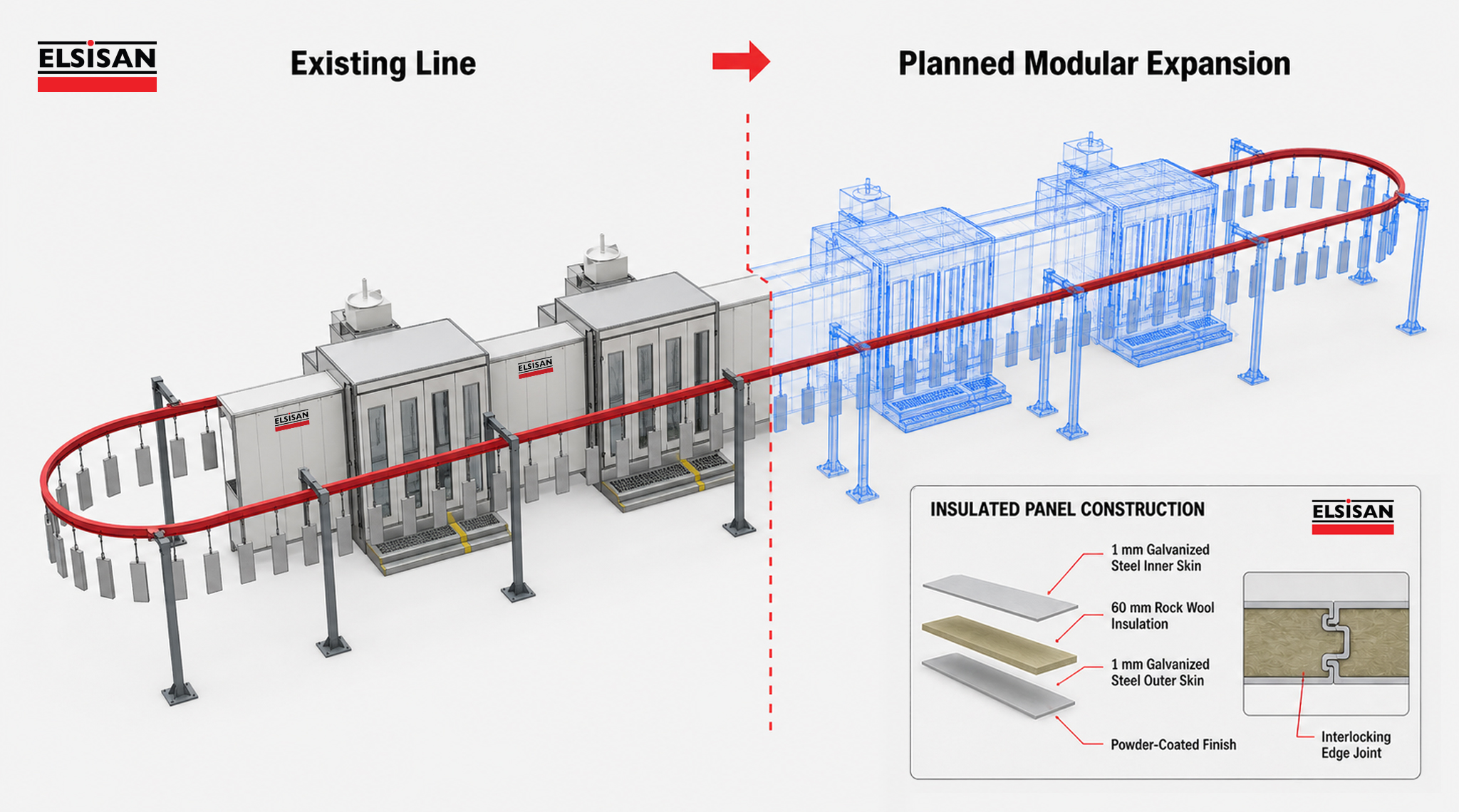
Existing coating line, planned modular expansion and insulated panel construction

This allows the existing system to adapt to different configurations without complete replacement when capacity increases, product dimensions change or the plant layout must be reorganised. Booths or process sections can be extended, the layout can be revised and existing structures can be repositioned with new equipment in a more controlled manner.

To plan this flexibility correctly, share not only current production volume but also, where possible, the expected growth over the next three to five years, planned new products and potential capacity-increase scenarios. The required infrastructure for later expansion and layout changes can then be anticipated from the start.

4. Select the Coating Application Method

4.1. Manual, Automatic, Robotic and Hybrid Coating Applications

The application method should be selected by considering not only production volume, but also product geometry, part diversity, colour-change frequency, difficult-to-reach surfaces, quality targets and the need for operator intervention.

Manual application can suit projects with high product variety, limited volumes or frequently changing geometries. The operator’s ability to adjust position and technique to the part provides valuable flexibility in low-volume and variable production.

Where products with similar geometries move at a regular production rhythm, automatic spray guns may be used. In automatic applications, the guns can be controlled using vertical gun movers (reciprocators), horizontal in/out positioners, or multi-axis motion systems configured for the product geometry. Product position on the conveyor, spacing, product height, conveyor speed, number of guns and target film thickness directly affect the automation design.

Robotic coating may be considered where complex geometries must be reached repeatably, coating recipes for different products must be stored and high process repeatability is required. Robot selection alone is not sufficient: reach envelope, booth dimensions, paint supply, part handling and positioning, safety equipment and control architecture must be engineered as an integrated system.

Automatic application should not be expected to cover every geometry and surface without support. Manual touch-up may be needed for deep recesses, internal corners, reverse surfaces, weld zones or areas affected by the Faraday cage effect during electrostatic application.

For this reason, many plants use hybrid coating systems rather than exclusively manual or automatic application. Automatic guns coat broad, accessible surfaces while an operator completes complex or difficult areas. This combines the speed, repeatability and transfer efficiency of automation with the geometric flexibility of manual application.
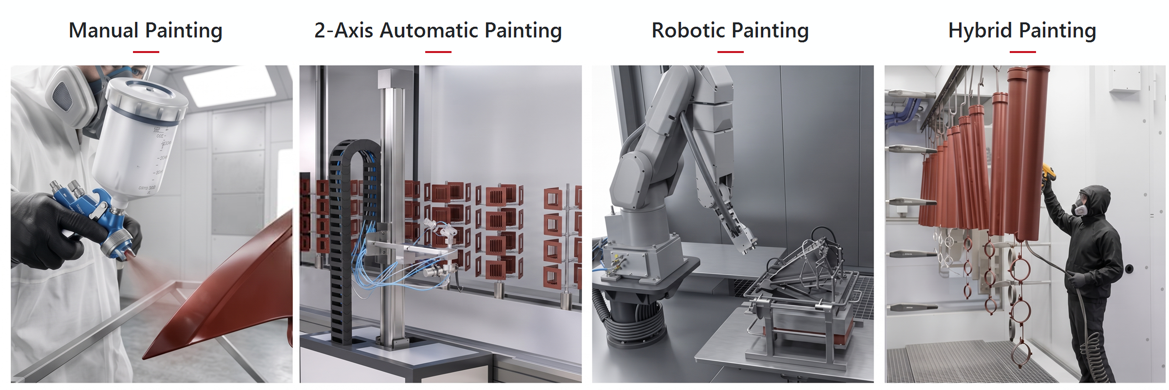
Manual, automatic two-axis, robotic and hybrid coating application methods

At Elsisan, we develop the application architecture around product geometry, production speed, colour-change frequency and target coating quality. Where required, we plan hybrid systems supported by manual touch-up, gun-moving systems adaptable to different product groups and infrastructure that can accommodate future automation.

5. Define the Process Flow

Once the product characteristics, production capacity and application method have been defined, the process flow can be established.

A typical industrial coating line may include the following stages:

  1. 01 Loading Placing the product on its hanger or carrier
  2. 02 Pre-treatment Mechanical, chemical or external process
  3. 03 Coating Application Single- or multi-coat application
  4. 04 Flash-off According to solvent and process requirements
  5. 05 Drying / Curing Final or intermediate curing
  6. 06 Cooling After a heated process
  7. 07 Unloading Removing the product from its hanger or carrier

Note: This is an example process sequence. Depending on the coating system and layer structure, pre-treatment may be performed outside the line; coating application, flash-off and intermediate curing stages may be repeated, or some stages may be omitted.

The process sequence may vary according to the coating type and product characteristics.

Where mechanical surface preparation is sufficient, a chemical pre-treatment line may not be required. In liquid-paint systems one or more flash-off zones may be positioned between primer and topcoat applications, or separate booths may be used for different layers. In standard powder-coating applications, the product is generally transferred directly to the curing oven after application, so a separate flash-off process is normally unnecessary.

The process flow should therefore not be copied from a standard template. It must be developed for the project according to the product’s surface condition, coating type and application method, production capacity and quality targets.

6. Select the Right Material Handling System

The material-handling system moves products between pre-treatment, coating, drying, curing and other processes. Its selection therefore directly affects line capacity, layout and process continuity.

The handling system should not be selected from product weight alone. Product dimensions, hanger pitch, line speed, curve radii, elevation changes, loading and unloading times, inter-process accumulation requirements and product positioning must be evaluated together.

Depending on the project and process structure, the following solutions may be considered:

Handling SystemsHandling PrincipleTypical Applications
Overhead SystemsProducts travel on hangers or carriers connected to an overhead conveyor track.General industrial lines where clear floor space is preferred
Floor-Mounted SystemsProducts travel on a floor chain, spindle or skid.Wheels, plastic parts, automotive components and large or heavy products
Power-and-Free /
Accumulation Systems
Carriers can be stopped, accumulated, separated and moved at different speeds.  Lines requiring different process times, buffers or product routing
Dip-Type Handling SystemsProducts are immersed in process tanks and transferred to the next station.Chemical pre-treatment, dip coating and KTL/e-coat processes
Manual / Semi-Automatic HandlingProducts are moved between stations by operators or simple mechanical equipment.Low-capacity, batch-type or high-mix plants
Special Handling SystemsProject-specific transfer solutions are developed.Special products and processes not suited to standard handling systems
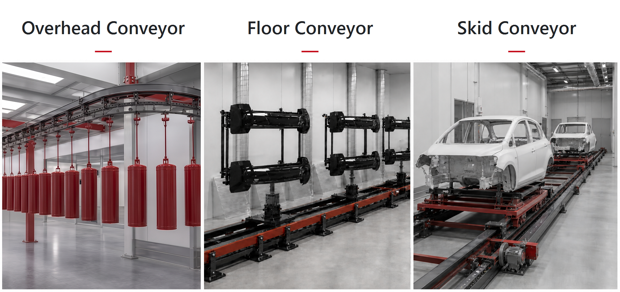
Overhead conveyor, floor conveyor and skid conveyor systems

No single handling system is suitable for every coating-line project. The correct solution depends on product characteristics, process structure, production rhythm and future operating scenarios. Proper planning helps balance process times, organise loading and unloading and maintain continuous operation at the target capacity.

7. Main Sections of an Industrial Coating Line

The equipment used in a complete industrial coating line is determined by the product characteristics, production capacity and selected process. Depending on the project scope, the following main systems may be evaluated together.
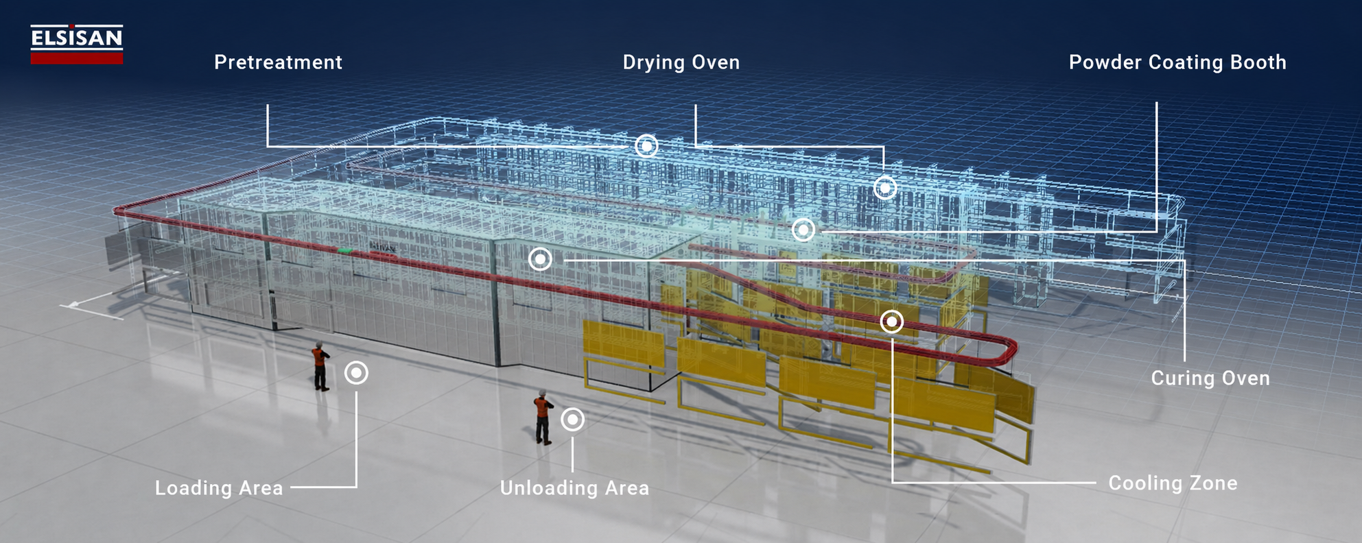
General industrial coating line layout showing pretreatment, drying, powder coating, curing, cooling, loading and unloading areas
Representative coating-line layout; equipment arrangement and process stages vary according to project requirements.

7.1. Pre-treatment System

Spray pre-treatment lines, dip tanks, enclosed chamber systems, parts washers or mechanical preparation solutions may be used to prepare products for coating. The method is selected according to product material, existing surface condition, required cleanliness and coating-system requirements.

Related content: Pre-treatment Systems

7.2. Coating Booth and Application Equipment

The coating booth is selected according to product dimensions, coating type, application method, production capacity and available workspace. Depending on the project, liquid-paint or powder-coating booths for manual, automatic or robotic application may be integrated with spray guns, reciprocators, robots, paint-supply units, recovery systems and manual touch-up stations.

Related content:

7.3. Drying and Curing Ovens

Water-drying, liquid-paint drying or powder-curing ovens may be used according to the project. Infrared (IR) or ultraviolet (UV) technologies may also be considered where appropriate. Oven selection should be based on product dimensions and weight, hourly load, coating specification, target product temperature, process time, conveyor speed, available space and energy infrastructure.

Related content:

7.4. Ventilation and Air-Conditioning Systems

Ventilation and air-conditioning systems are engineered to maintain the required air quality, temperature and humidity in the booth and related process areas. Supply and exhaust airflow, filtration stages, booth pressure balance, temperature and relative humidity are determined according to the coating type, product characteristics, process requirements and factory environment.

Heating, cooling, dehumidification or humidification may be integrated as required. Correct air conditioning helps maintain coating quality, reduce surface defects and improve process repeatability.

7.5. Energy Efficiency and Heat Recovery

Energy efficiency depends not only on equipment selection, but also on how heat and conditioned process air are managed between processes. Ovens, drying sections, coating booths and air-conditioning systems should therefore be considered together in terms of energy flow.

Depending on the project, hot air from ovens, heat in exhaust air or conditioned process air may be recovered at different points. Where suitable, this energy can preheat fresh air, support another process or reduce total demand. The objective is not merely to choose lower-consumption equipment, but to build a more efficient process by evaluating where energy is generated, used and discharged throughout the plant.

7.6. Automation System

A PLC- and HMI-based automation system enables line equipment to operate under a common process scenario, allows critical parameters to be monitored and provides centralised control. Depending on the project, RFID, barcode or similar identification can track products along the line and automatically call product-specific process recipes. SCADA systems can monitor, record and report process data.

At Elsisan, we engineer the automation architecture around the plant’s control, traceability and efficiency requirements, developing project-specific solutions that integrate mechanical equipment and control systems.

8. Pre-Quotation Information Table

To prepare a technical quotation around actual production conditions, provide the following information using current, measurable data wherever possible.

Information to PrepareDetails Required for Quotation
Product DataTechnical drawings, minimum and maximum dimensions and part weight for each product family.
Material and SurfaceMaterial such as steel, aluminium or plastic, plus whether the surface is oily, corroded or pre-treated.
Coating and MaskingMarked drawings showing surfaces to be coated and areas to be protected, contacted or masked.
Capacity and GrowthHourly, daily and annual targets, shift pattern and expected capacity increase.
Coatings and ChemicalsPowder or liquid coatings and process chemicals, with current technical and safety data sheets where available.
Colour ManagementNumber of active colours, batch size and daily or weekly colour-change frequency.
Quality TargetsFilm thickness, appearance, adhesion, corrosion resistance and acceptance criteria.
Space and LayoutAvailable net area, ceiling height, column and door positions and preferred product flow.
UtilitiesAvailable capacities and connection points for electricity, gas, water, compressed air and exhaust.
Automation and TraceabilityRequirements for recipe management, data logging, alarms, reporting and ERP/MES integration.
Environment and SafetyApplicable environmental conditions, fire scenario, ATEX requirements and worker-exposure conditions.

8.1. Start the Quotation Process with the Right Data

Share the information already available; missing technical inputs can be clarified together during a preliminary review with the Elsisan engineering team.

Contact us about your project and start the quotation process.
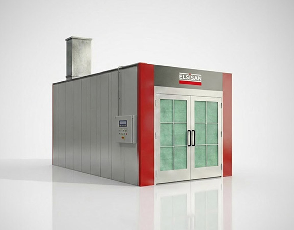
How to Choose an Enclosed Dry Filter Spray Booth: Types and Configurations Explained

Engineering Principles and Industrial Applications of different spray booth designs


Introduction

Enclosed spray booths are engineered painting environments designed to provide controlled airflow, contamination prevention, and consistent coating quality. By managing air movement, filtration, and extraction systems, these booths ensure efficient overspray removal while protecting both the operator and the surrounding environment.

The selection of booth configuration depends on required finish quality, production volume, available space, and investment level. The three most common airflow configurations are Cross Draft, Side-Downdraft, and Full Down (Downdraft) systems. This article focuses on dry filter spray booth systems. For a detailed overview of filtration types used in spray booths, see our dedicated article: Filtration Types in Spray Booths.

1) Spray Booth Types

Let’s examine different spray booth types and have a quick overview of different models.

A) Cross Draft Spray Booths

The Cross Draft system is the most economical enclosed spray booth configuration. It operates with horizontal airflow across the working area. Due to its simple design and cost efficiency, it is widely used in general industrial applications.

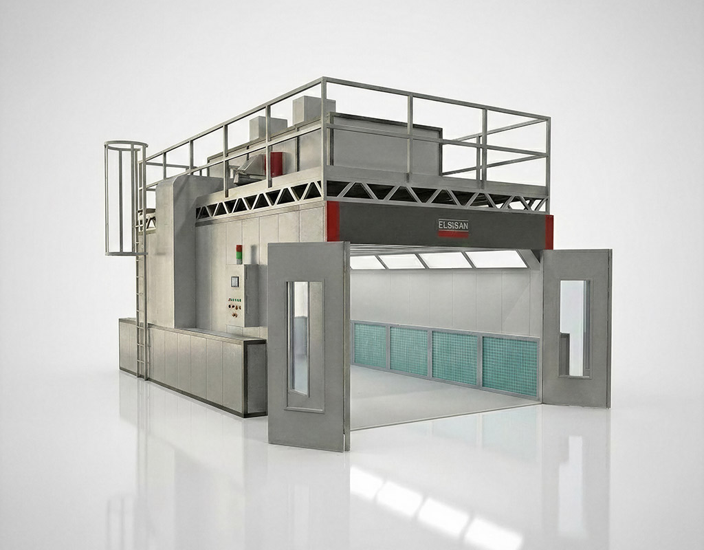
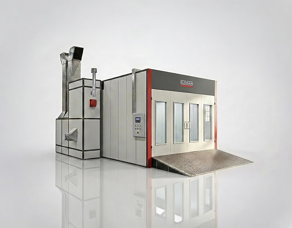
Cross draft dry filter spray booth

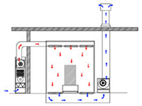
Air Flow Principle

Air enters from one wall and moves horizontally across the painted object before being extracted from the opposite wall.

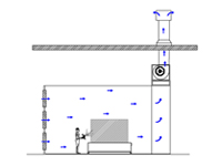
Cross draft spray booth airflow diagram

Advantages

  • Lower investment cost compared to other models
  • No pit requirement like the downdraft floor pits

Recommended Applications Areas

  • Suitable for parts that are painted from one direction.
  • Industrial equipment
  • Medium-quality coating processes

B) Side DownDraft System

A Side Downdraft Spray Booth is a painting system where filtered air enters from the ceiling and moves downward over the workpiece, then is extracted through exhaust filters located on the lower side walls of the booth. It provides near-downdraft performance without requiring a full floor exhaust system.

Side downdraft dry filter spray booth

Airflow Principle

Fresh filtered air enters through ceiling filters. Air flows vertically downward over the painted object. Contaminated air and overspray are drawn toward the lower side wall exhaust filters. The airflow combines vertical downward movement with side extraction.

Side downdraft spray booth airflow diagram

Advantages

  • No need for a full floor pit system
  • Lower installation cost than full downdraft
  • Suitable for large and heavy objects

Recommended Application Areas

Customers who don’t prefer pit construction work and cannot have construction in their factory floors for a downdraft airflow. Suitable for large and heavy products that may require strong flooring.

  • Industrial manufacturing plants
  • Large metal structures
  • Truck and bus painting

C) Full Down (Downdraft) System

The Full Down or Downdraft system represents a high level of airflow control in enclosed spray booths. It is designed to provide uniform vertical airflow from ceiling to floor, ensuring high contamination control and superior surface quality.

Full downdraft dry filter spray booth

Airflow Principle

Filtered air is distributed evenly through the full ceiling plenum. The airflow moves vertically downward across the painted object and is extracted through a grated floor connected to an exhaust pit system. This vertical airflow pattern minimizes turbulence and prevents overspray from contacting freshly coated surfaces.

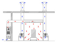
Full downdraft spray booth airflow diagram

Advantages

  • High coating quality
  • Excellent airflow uniformity
  • High overspray removal efficiency

Recommended Applications Areas

Customers that can built pit construction or can have their spray booths elevated from the ground to accomodate the floor suction.

  • Automotive OEM production
  • Aerospace components
  • High-gloss industrial finishing
  • Class A surface coating processes

2) Part Handling Systems in Spray Booths

A. Overhead Carrying System Constructed Inside the Booth

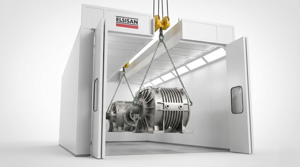
The Overhead Carrying System transports parts through the spray booth using suspended conveyors mounted on the ceiling structure. Components are hung from carriers and move along a predefined track path.

Interior overhead conveyor crane system inside a spray booth

Working Principle

Parts are attached to hooks or fixtures and conveyed via a motor-driven rail system installed above the working area. This keeps the floor area clear and allows continuous production flow.

Advantages

  • No additional openings in the booth structure required, preserving the integrity of the controlled environment
  • Compatible with ATEX-certified explosion-proof configurations for solvent-based coating environments
  • Enables continuous production flow with minimal manual intervention
  • Parts can be rotated during conveying to allow coating from multiple angles without stopping the line

B. External Overhead Bridge Crane System

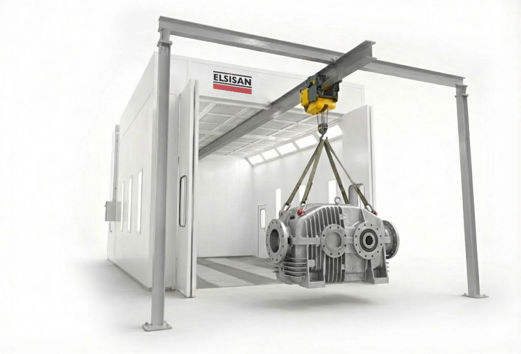
An External Overhead Bridge Crane System uses a crane installed on rails above and outside the spray booth structure to lift and position workpieces into the booth. This approach eliminates the need for an internal conveyor system while still enabling the handling of very large or exceptionally heavy components.

External overhead bridge crane system used for part handling in spray booths

Working Principle

Workpieces are lifted by an external bridge crane using hooks, chains, or spreader beams. The crane travels along rails positioned above the booth and lowers the part directly into the booth through large access doors or an open-top design. After coating, the crane lifts the part out and transports it to the next production stage. A single crane can serve multiple booths or work areas, improving overall production flexibility.

Advantages

  • Handles very large and extremely heavy workpieces
  • No internal conveyor installation required inside the booth
  • One crane can serve multiple booths or production areas
  • Lower booth investment compared to fully integrated conveyor systems
  • Flexible for varying part sizes and geometries

C. Floor Ground Rail System

The Floor Ground Rail System moves parts using rail tracks embedded in or mounted on the floor. Carts or platforms transport heavy components through the booth.

Floor ground rail transport system inside a spray booth

Working Principle

Workpieces are placed on wheeled trolleys that travel along floor-mounted rails. This system is particularly suitable for large and heavy components.

Advantages

  • High load carrying capacity
  • Suitable for heavy-duty applications
  • Stable and secure transport
  • Easier maintenance access

D. Manual Wheeled Cart System

The Manual Wheeled Cart System is the simplest and most cost-effective part handling method. Workpieces are loaded onto wheeled carts or platforms and manually pushed into the spray booth by operators. This approach requires no powered drive systems or fixed infrastructure, making it easy to implement in any booth configuration.

Working Principle

Parts are loaded onto wheeled carts or dollies at a preparation area outside the booth. Operators manually push the loaded carts through the booth doors and position them for coating. Once the painting process is complete, the carts are rolled out to a drying or curing area. No electrical connections or fixed guide tracks are required.

Advantages

  • Lowest investment and installation cost
  • Minimal maintenance requirements
  • Maximum flexibility for different part types and sizes
  • No special floor infrastructure or electrical systems required
  • Easy to reconfigure or expand production layouts

3) Spray Booth Door Types

The door system of an enclosed spray booth determines how parts enter and exit the coating area. The right door type depends on part size, production flow, and available floor space.

A) Manual Hinged Front Doors

Manual hinged doors are the simplest and most cost-effective entry solution for enclosed spray booths. They swing open on hinges and are operated by hand, making them suitable for low-volume production or smaller booths where automated access is not required.

  • Low investment and maintenance cost
  • No mechanical drive system required
  • Suitable for smaller parts and lower production throughput
Manual hinged front doors for spray booth

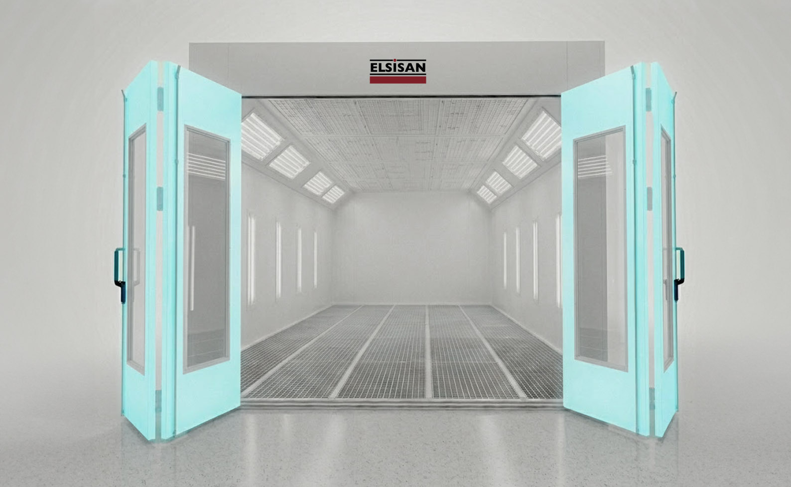
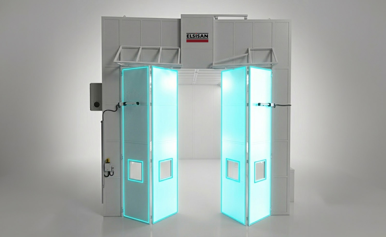
B) Automatic Motorized Bi-Fold Doors

Motorized bi-fold doors open by folding in two sections, significantly reducing the floor space required for door swing. They operate electrically and can be integrated with the booth control system for automatic opening and closing during production cycles.

  • Compact opening footprint suitable for space-constrained facilities
  • Fast cycle times for continuous production flow
  • Can be interlocked with booth ventilation and control systems
Automatic motorized bi-fold doors for spray booth

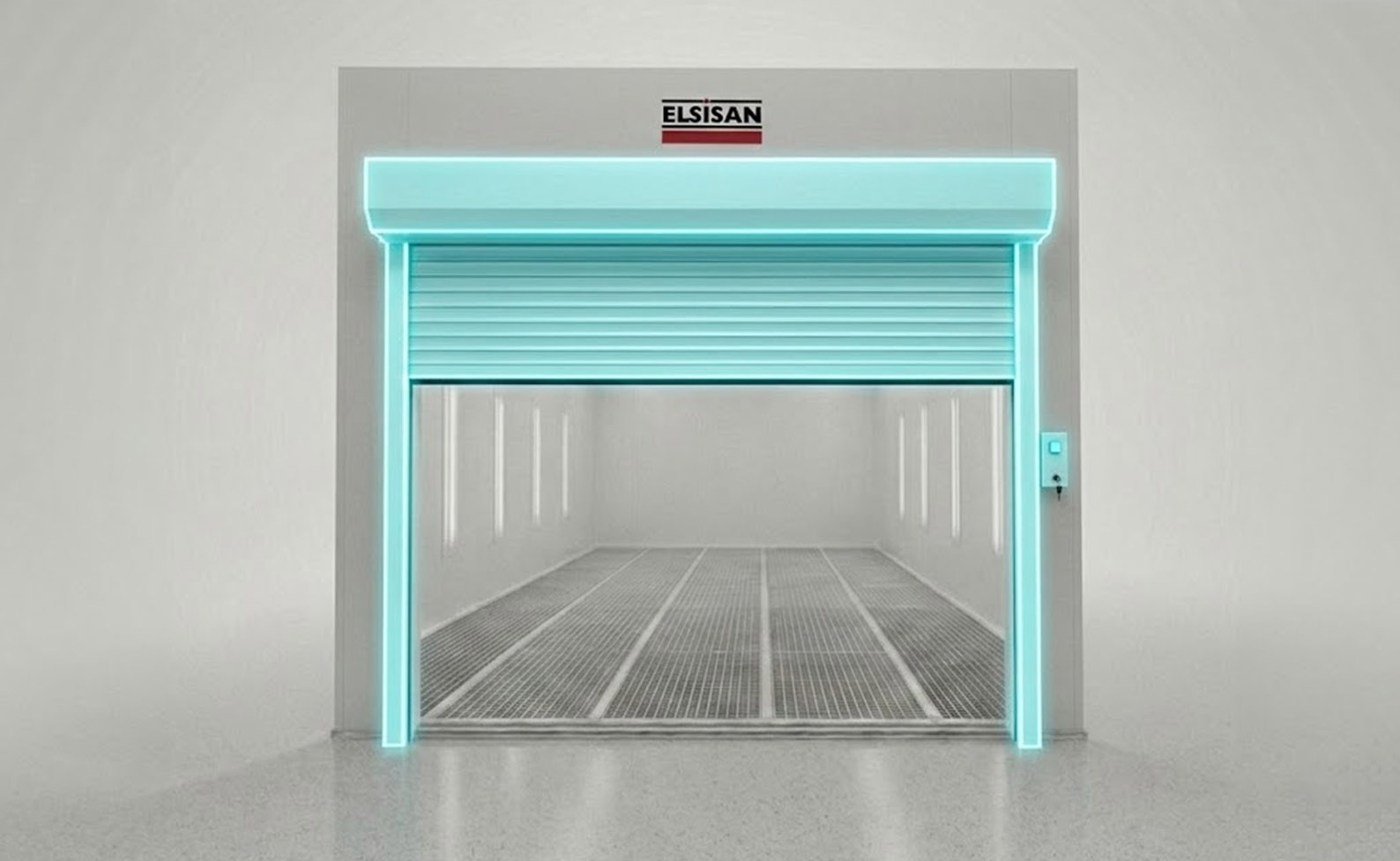
C) Roller Doors

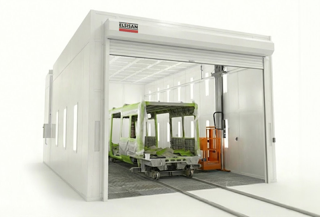
Roller doors are a highly space-efficient solution for spray booths that require large access openings. The door rolls upward into a drum mechanism mounted above the opening, keeping the entire floor area completely clear. They are especially preferred for large and heavy workpieces or vehicle-sized products.

Elsisan spray booth roller door system
  • Maximizes clear opening width and height
  • No floor space consumed by door swing
  • Suitable for large workpieces and vehicle-sized parts

4) Positive and Negative Pressure Booths

A) Positive Pressure Booths

In a positive pressure booth, both supply (intake) fans and exhaust fans are active, with the supply airflow slightly exceeding the exhaust. This creates an internal air pressure that is marginally higher than the surrounding environment. As a result, air is continuously pushed outward through any gaps or openings in the booth structure, preventing unfiltered outside air, along with the dust particles it carries, from entering the painting area.

Positive pressure spray booth diagram

This design delivers a cleaner, more controlled coating environment, making it the preferred choice for applications with high finish quality requirements. The trade-off is a higher initial investment, as the system requires both supply and exhaust fan assemblies along with more sophisticated air balancing controls.

B) Negative Pressure Booths

A negative pressure booth uses only exhaust fans, which draw air out of the booth and create an internal pressure slightly below the surrounding environment. Fresh air enters through dedicated filtered intake openings to replace the exhausted air. Because the booth is under negative pressure, any unintended gaps or openings in the structure will draw in unfiltered ambient air, increasing the risk of dust contamination on freshly coated surfaces.

Negative pressure spray booth diagram

While this configuration is simpler and less costly to install, it is more sensitive to the condition and integrity of the booth enclosure. It remains a practical and widely used solution for coating operations where the highest level of cleanliness is not the primary requirement.

5) Air Handling Units (AHU) in Enclosed Spray Booths

Air Handling Units (AHUs) are responsible for depending on the customer requirements they can be equipped to control air quality, temperature and humidity inside the spray booths. Their main purpose is to ensure stable coating conditions, consistent drying performance, and optimal working environment. AHU units are located before the intake air and are categorized under the pressurized spray booth types. (Which means rather than having a simple intake fan, these handling units can refine the air in more advance requirements for customer requirements)

A) Heating Systems

  • Heating outside air
  • Maintain constant spraying temperature
  • Accelerate paint drying and curing process
  • Ensure stable operation during cold weather

How It Works

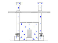
Fresh outside air is drawn in, warmed as it passes through the heating unit, and then supplied into the spray booth through the intake filters.

Spray booth heating systems generally operate using one of the following methods:

a1) Direct Gas Burner System

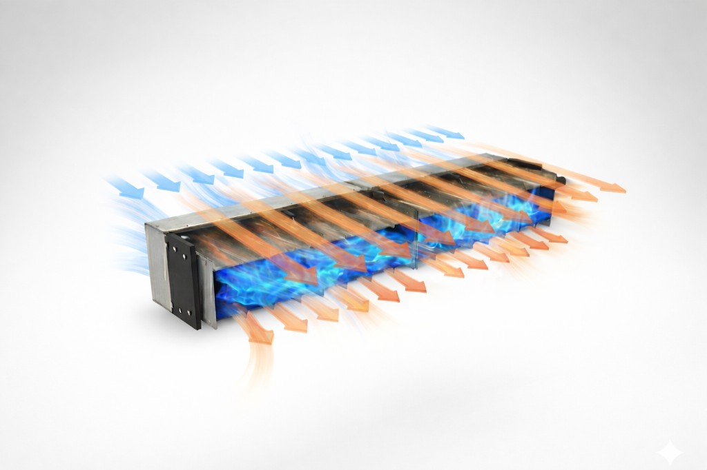
In a direct gas burner system, natural gas or LPG is combusted directly within the air stream that enters the spray booth. The flame heats the airflow as it passes through the burner chamber, and the resulting hot air is supplied directly into the booth. This is one of the most thermally efficient methods, as there is no intermediate heat transfer step.

Direct gas burner system for spray booth heating
  • Natural gas or LPG is burned directly in the airflow path
  • The heated air is supplied directly into the booth
  • High thermal efficiency

a2) Indirect Gas Heating System

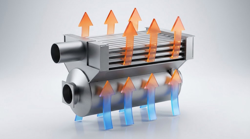
An indirect gas heating system combusts gas in a separate, sealed chamber. The heat generated is transferred to the incoming air through a heat exchanger, so the combustion exhaust gases never come into contact with the process air entering the booth. This keeps the airflow clean and free from combustion by-products.

Indirect gas heating unit with heat exchanger for spray booth
  • Combustion occurs in a separate chamber
  • Heat is transferred through a heat exchanger
  • Exhaust gases do not mix with process air
  • Provides cleaner airflow into the booth

b) Electric Heating System

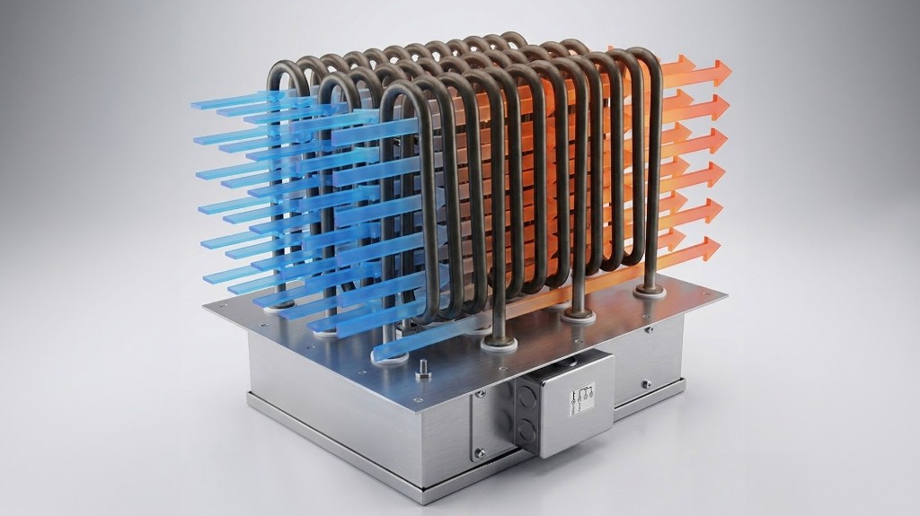
Electric heating systems use resistance heating elements to warm the incoming air before it enters the booth. There is no combustion involved, which simplifies installation and removes the need for gas supply infrastructure. This makes electric heating particularly practical for smaller installations or locations where gas supply is not available.

  • Electric resistance heaters warm the air
  • No combustion or gas supply required
  • Simple installation and low maintenance
Electric heating system for spray booth

c) Hot Water and Steam Heat Exchanger Systems

Hot water and steam heat exchanger systems heat the incoming air indirectly by passing it over a coil or heat exchanger that carries hot water or steam from a central boiler or district heating network. The combustion or heat generation happens remotely, and only the heated medium is circulated to the spray booth unit.

  • Clean and safe heating with no combustion inside or near the booth
  • Well suited for facilities that already operate a central boiler system
  • Consistent and stable heat output

B) Cooling Systems

The purpose of the cooling systems is to prevent overheating during summer conditions or in hot climates, to maintain stable temperature to stabilize paint viscosity, and to improve operator comfort. Cooling is typically achieved through chilled water coils or direct expansion (DX) refrigeration units integrated into the AHU assembly.

  • Prevents overheating in high-ambient-temperature environments
  • Maintains stable paint viscosity for consistent application results
  • Improves operator working conditions during summer operation

C) Humidification Systems

Humidity control in a spray booth affects finish quality, paint behavior, and dust management. Both extremes are problematic: air that is too dry causes static buildup, dust attraction, and dry spray as paint skins too quickly; air that is too humid slows solvent evaporation, increases the risk of sags and runs, and can trap moisture beneath clear coats. Waterborne paints are particularly sensitive to humidity, as high relative humidity (RH) significantly delays flash-off and can cause mottling and extended cycle times.

  • Reduces static electricity buildup and airborne dust attraction on freshly coated surfaces
  • Prevents dry spray and poor leveling caused by excessively dry air
  • Critical for waterborne paint lines where tight RH control is often required by paint supplier or OEM specifications
  • Eliminates seasonal coating quality variation, particularly during winter heating cycles when indoor humidity drops significantly

6) Automation and Control Systems in Enclosed Spray Booths

Automation and control systems in enclosed spray booths are designed to ensure process stability, safety, energy efficiency, and consistent coating quality. These systems integrate mechanical components, sensors, and programmable logic controllers (PLC) to maintain precise environmental and operational conditions. Advances systems can include Scada and additional features on customer requests. Here is a quick overview of the features.

Core Automation Components

PLC (Programmable Logic Controller)

The PLC serves as the central control unit. It monitors system inputs and controls outputs such as fans, burners, dampers, and heating elements according to programmed logic.

Sensors

  • Temperature sensors
  • Humidity sensors
  • Pressure sensors
  • Airflow switches
  • Gas detection sensors (Upon request)

These provide real-time data for closed-loop control.

Airflow and Pressure Control

Automation systems regulate:

  • Supply fan speed (via VFD – Variable Frequency Drive)
  • Exhaust fan speed
  • Damper positions

This ensures:

  • Balanced airflow
  • Controlled positive pressure inside the booth
  • Prevention of dust infiltration

Pressure Sensors and Automatic Filter Replacement Alert Feature

Differential pressure sensors are used to continuously monitor filter loading. As a dry filter accumulates overspray and particles, the pressure drop across the filter increases. When the pressure difference reaches a set threshold, the system triggers an alarm to notify the operator that the filter needs to be replaced. This prevents degraded airflow, inconsistent booth pressure, and reduced capture efficiency, all of which directly affect finish quality.

Operational Modes

Automation enables different predefined modes:

Spraying Mode

  • Lower temperature
  • Balanced airflow
  • High filtration efficiency

Curing Mode

Curing mode is only available on booths equipped with a heating unit.

  • High temperature
  • Recirculated airflow
  • Reduced fresh air intake for energy efficiency

Energy Efficiency Features

Modern automation systems include:

  • Variable Frequency Drives (VFD)
  • Air recirculation control
  • Proportional burner control
  • Heat recovery systems (Can be added upon request)

These reduce operational energy costs while maintaining performance.

7) Conclusion

Enclosed spray booths are engineered systems designed to ensure controlled airflow, stable environmental conditions, and consistent coating quality across industrial applications. The selection of appropriate airflow configuration — Cross Draft, Side Downdraft, or Full Downdraft — directly influences finish performance, contamination control, and operational efficiency.

When supported by integrated part handling systems, advanced Air Handling Units (AHU), and PLC-based automation, enclosed spray booths provide precise temperature, pressure, and humidity management throughout all operational modes. This integrated approach enhances product quality, improves workplace safety, and optimizes energy consumption.

In modern industrial environments, enclosed spray booths function not only as painting enclosures but as fully controlled process systems that deliver reliability, repeatability, and long-term production efficiency.

Industrial Batch Ovens: Options and What You Need to Know

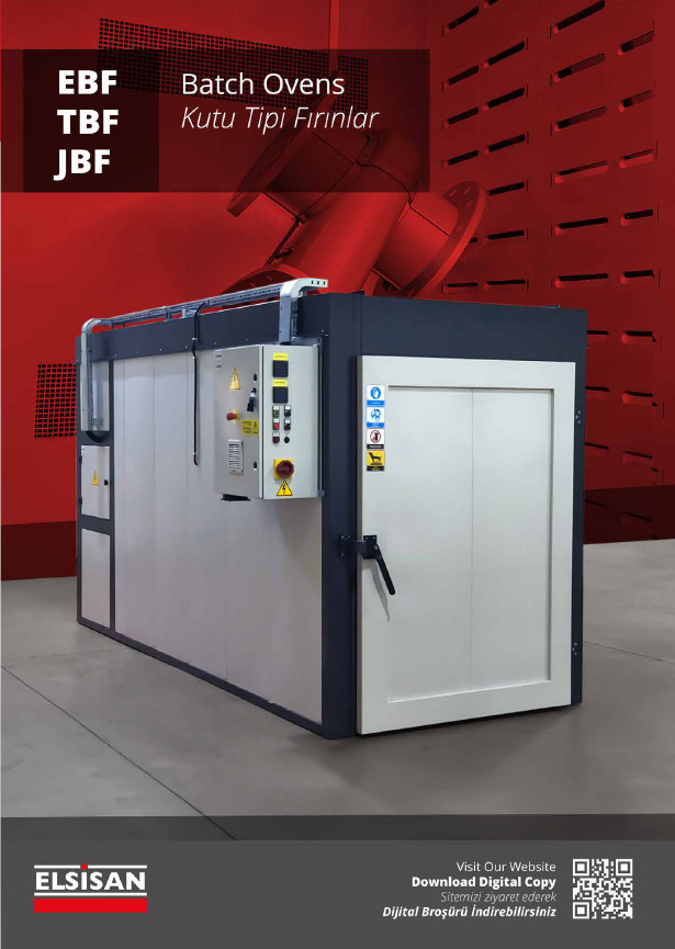
Batch ovens are industrial ovens designed for processing materials or products at a specified temperature for a set period. They are used for various processes such as baking, drying, curing, or heat treatment by bringing the product to a specific temperature. These ovens, designed based on factors such as product size, process requirements, and production volume, play a critical role in industrial production processes.

Application Areas:

Batch ovens have a wide range of applications in industrial production processes. General application areas are listed in processes;

Drying applications used in batch ovens, remove moisture from materials before processing and prepare their surfaces. This ensures more solid and high-quality results in subsequent processes. For products with high moisture content, higher-powered exhaust systems are used for quick moisture removal.

Curing application in batch ovens, the solvent vapors on painted surfaces evaporate with hot air, solidifying to form a film. In powder coating processes, these ovens cure powder coating materials, providing a durable coating through precise temperature and time control.

Heat Treatment application in batch ovens used in metallurgy and metal processing industries to alter the physical or mechanical properties of materials. Processes such as annealing, tempering, and stress relief can be applied.

Box ovens with various applications play a significant role in enhancing quality, durability, and efficiency in industrial production processes. As Elsisan, our box ovens are designed to reach operational capabilities of up to 250°C.

Sections of Box-Type Ovens:

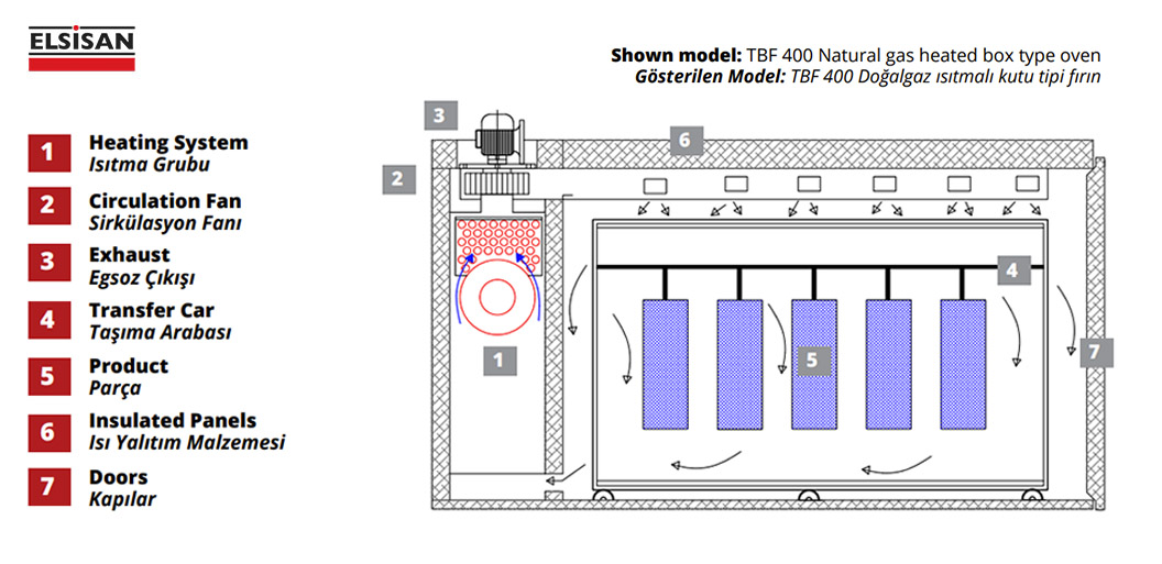
Below, the features and components of batch ovens are shown as illustrated in Figure 1.

1. Heating System

2. Circulation Fan 

3. Exhaust

3. Transfer Car   

5. Product 

6. Insulated Panels

7. Doors

TBF 400 Doğalgaz ısıtmalı kutu tipi fırın

Features:

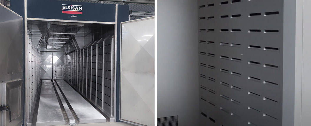
Adjustable Channels:

Adjustable air channels ensure even heat distribution throughout the oven.

Industrial batch ovens - adjustable air vents

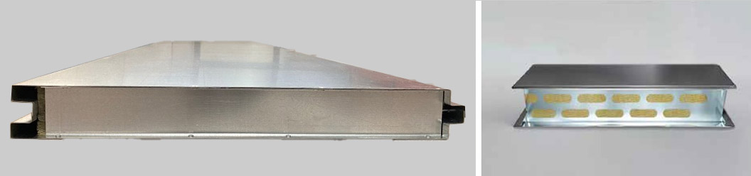
Insulated Panels:

In batch ovens, insulated panels reduce heat loss and maintain temperature values, enhancing thermal efficiency. Insulation material is placed between galvanized steel sheets, with rock wool used as standard. The thickness of the insulation material varies depending on the desired maximum temperature. Panels are coated with powder paint in the desired color and assembled in a sandwich panel format.

Industrial batch ovens - Thermally insulated panels

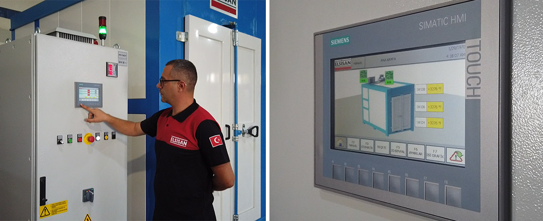
Control Panel:

The control panel of batch ovens comes with a touchscreen interface. The PLC control panel allows for recipe management, temperature and time adjustments, and sensor data reading. The system is controlled via sensors that monitor internal temperature, fan airflow, and exhaust temperature. The PLC control panel also enables stepwise adjustments over time and provides alerts if products are not removed after baking, preventing overexposure to heat.

Industrial batch ovens - control panel

Customization Options:

We can customize our products in various ways according to your needs. Below you can find detailed information about these customization options.

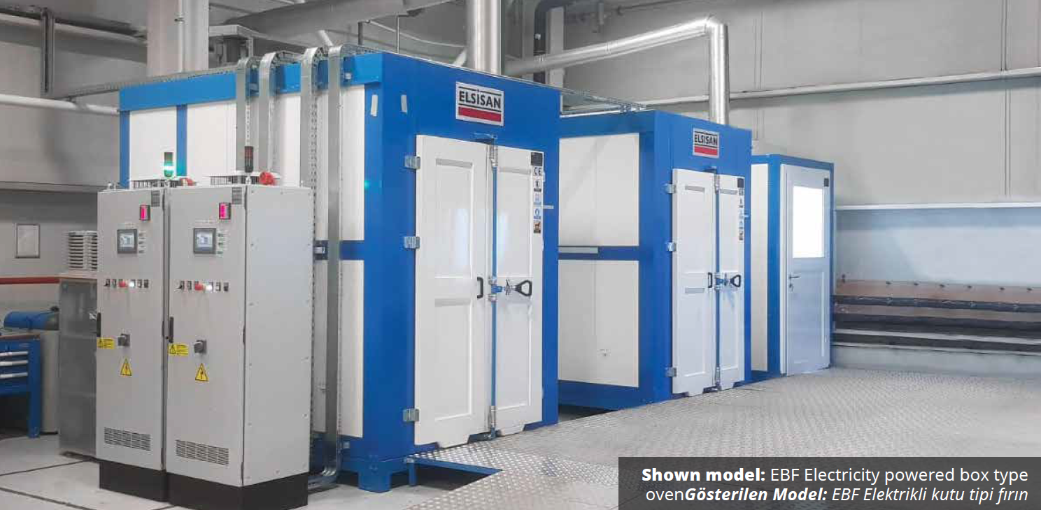
Şekil 4. EBF Elektrik ısıtmalı kutu tipi fırın

Airflow Options:

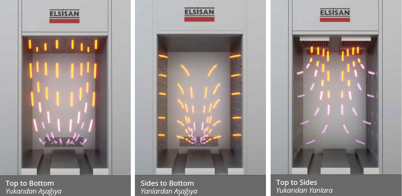
As Elsisan, we offer various airflow options to increase process efficiency with industrial batch ovens. They are designed to suit your needs. Air channel vents can be manually adjusted to ensure good heat distribution. Below, you will find air flow options such as top to bottom, side to bottom and top to side shown as examples. Different air flow types can be designed to fit your needs.

Air circulation in the oven is provided by a fan. Thanks to the air channels extending along the oven and the vents placed on the ducts, a homogeneous heat distribution is achieved in the oven.

Şekil 5. Hava akış yönü seçenekleri

Transport Options:

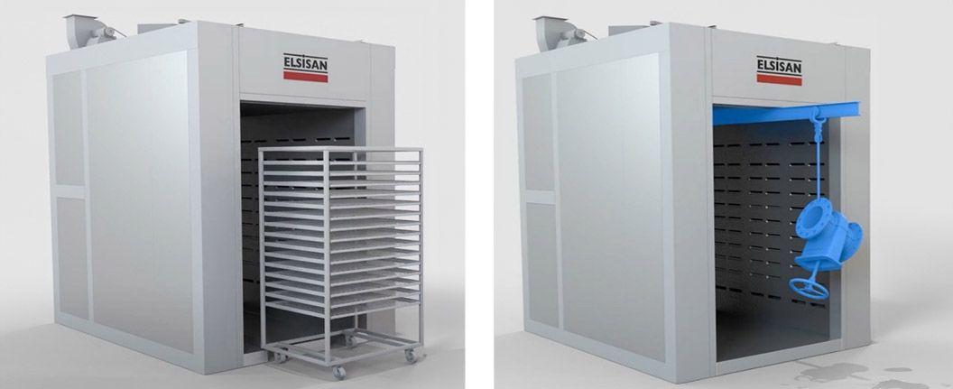
Batch ovens can be offered different transportation options depending on the number of products you want, the size and weight of the product. These options are mainly as follows;

  • Transport trolley that can move within the grooves opened on the oven floor
  • Manual overhead carrying system with I profile rail on the ceiling.
  • Ground rail transportation system.

Custom transport systems can also be designed according to your needs.

Şekil 6. Kutu arabalı ve Havai raylı taşıma sistemi

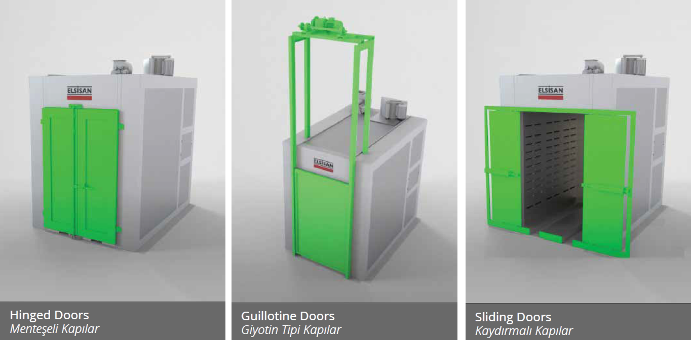
Door Options:

Ovens can be manufactured with different types of doors. We can determine the design of the doors according to the features of the production line. You can increase the functionality of your oven by choosing the model that suits your workflow and ease of access from our door type options.

  •  Hinged Doors
  •  Sliding Doors
  •  Guillotine Doors

Şekil 7. Menteşeli kapılar, Kaydırmalı kapılar ve Giyotin tipi kapı seçenekleri

Heating Options:

Batch ovens manufactured by Elsisan, provide efficient heating options tailored to your needs, adapting to different energy sources to meet your industrial needs.

Electric: Our electrically operated batch ovens generate heat through high quality serpentine resistors. Serpentine resistors directly convert electrical energy into thermal energy and provide heat distribution with fans inside the oven.

Natural Gas: Our batch ovens powered by natural gas provide energy through natural gas burners. The burners burn natural gas, provide high temperature combustion and transfer this energy into the oven, bringing your products to the desired temperature.

Steam: Steam heating options utilize existing steam lines. Energy from the steam exchanger heats the oven for your products. This method is suitable for large-scale facilities with easy access to steam.

Conclusion

As Elsisan, we provide various options to meet your industrial batch oven needs, helping you achieve effective production solutions. We prioritize high customer satisfaction and manage every aspect of the product lifecycle from design to delivery.

For more information and to request a quote, please contact the Elsisan team using the email address and contact information below. We look forward to assisting you in developing the best investment strategy for your company.
 

Batch Ovens Brochure

Web : elsisan.com
E-Mail : elsisan@elsisan.com

Spray Coating Lines for Glasses: Process Steps and Options

Glass manufacturing is evolving, with advancements in technology driving efficiency and quality to new heights. A standout in this transformation is Elsisan’s spray coating lines for glass products, which redefine precision and efficiency in glass painting. In this blog post, we’ll explore what you need to know before purchasing a glass spray coating line, and how these systems operate. Since all customer requirements are unique regarding part details, paint specifications, and space limitations, these lines are custom-made for our customers’ specific needs.

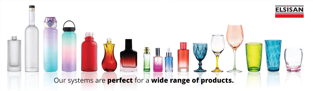
Which Parts Can Be Painted in Our Glass Spray Coating Lines?

  • Glass bottles
  • Bottle closures
  • Fragrance bottles and vials
  • Plastic bottles
  • Beverage bottles

And much more! Our systems are perfect for a wide range of products, and are not limited to the ones mentioned above.

Spray coating lines for glass - Glass products plastic bottles glasses

Things You Must Know Before Starting:

  1. Part Dimensions:
    We need to know the minimum and maximum dimensions of your parts. This helps design the conveyor and the spacing of part holder jigs to enhance your efficiency. Part dimensions will determine several other factors as well, such as door openings, spray coating equipment placement, and painting booth dimensions.
  2. Desired Capacity:
    To accurately tailor your spray coating line for optimal performance, we need to specify your desired production capacity in units per hour. This will optimize your investment cost and line efficiency. Having a larger capacity than needed will result in inefficient and expensive line investment and operating costs.
  3. Paint Technical Requirements (TDS Document):
    It’s important to choose your paint chemicals before starting the design of your painting line. After you choose your paint, companies will provide a Paint Technical Data Sheet (TDS), which will provide information about specific requirements such as paint application environment requirements, flash-off and curing times, and requirements. If you haven’t yet chosen your paint, the Elsisan team can recommend you a list of local and global companies who have expertise in this area to determine your paint chemicals and perform necessary laboratory tests.
  4. Available Factory Area:
    We need this information to determine the design of your machine. If there are any columns or obstructions in the area, or any other limitations in the space, we can work on different designs to solve and optimize your painting line design. It’s also important to consider loading and unloading areas and parts stocking areas.

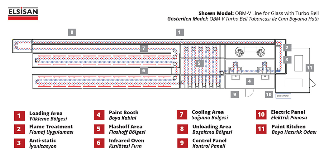
Sections of Glass Spray Coating Lines

After collecting the necessary information, we can start designing a spray coating line for glass. Let’s look at the usual sections of such a line:

1. Loading Area

2. Pre-treatment: Flame Treatment

3. Pre-treatment: Anti-static Application

4. Paint Booth

5. Flashoff Area

6. Curing Oven Area

7. Cooling Area

8. Unloading Area

9. Control Panel

10. Electric Panel

11. Paint Kitchen

spray coating lines for glass - sections layout 2d drawing

Loading Area

In the loading area, operators place the parts on top of part holding jigs which are specifically designed for customer’s parts. Some part holder jigs have different dimensions and masking areas to achieve customer’s requirements, so depending on the parts, the jigs may need to be changed. However, in most cases, universal part holder jigs can be designed to fit a variety of different products.

Pre-Treatment

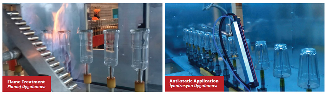
In glass coating applications, pre-treatment is an important step to achieve desired quality and durability. Therefore, two main pre-treatment applications are applied to parts:

1.Flame Treatment:
Flame application cleans and increases surface tension for better paint adhesion on glass and plastic, ensuring a durable, high-quality finish.

2.Anti-static Application:
Antistatic bars are used to neutralize static electricity, effectively removing dust and improving the quality of the paint applied.

Spray coating lines for glass - pretreatment antistatic flame treatment

Paint Spray Booth

Inside the spray booth area, paint is applied through paint equipment in a controlled environment. Depending on the specifications of the Paint Technical Requirements, it’s highly important to create the necessary environment in terms of humidity and temperature to achieve the desired quality. As mentioned, there will be airflow inside the spray booth, and this airflow will help catch and filter overspray particles. There are two main options to catch overspray particles:

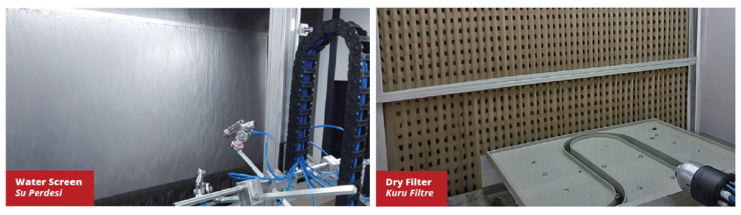
  1. Dry Filters:
    Dry filters offer a cost-effective, space-saving option, capturing overspray particles with fibrous materials.
  2. Water Screen:
    Water screens, ideal for high-volume use, use a water curtain to trap and purify, with optional sludge separation systems.

Spray coating lines for glass - spray booth dry filter water screen wet paint filter copy

Another vital aspect of spray booths is choosing the right equipment for your spray application to achieve desired effects and efficiency. Here’s what’s commonly used in spray glass coating applications:

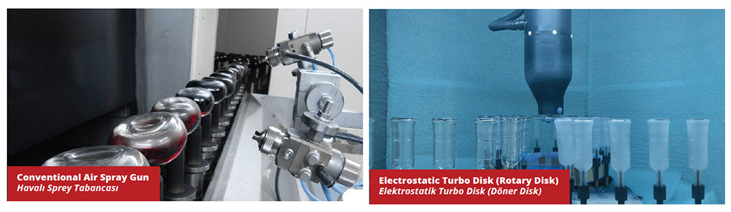
  • Conventional Air Spray Gun
  • Electrostatic Spray Gun
  • Electrostatic Turbo Disk (Rotary Disk
  • Electrostatic Turbo Bell (Whirling Cup)

Spray coating lines for glass - spray booth paint application styles coating equipment

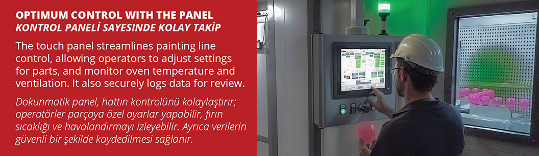
It’s also important for an operator to easily control and track the operations inside the spray painting booth, such as paint equipment stroke movements, filter changes, airflow, etc. That’s why a touch panel will be located right outside the spray painting booth in a position where the operator can easily see inside the spray booth through glass and make necessary adjustments and controls. It will also securely log data for future reviews.

Spray coating lines for glass - spray booth control panel

Flashoff Area

In the flashoff area, necessary exhaust and airflow will be created to achieve solvent evaporations. A certain amount of time needs to be spent in the flashoff area before the curing process can start.

Curing Area

In glass coating lines, the curing phase is crucial to achieve the desired quality and durability of the paint application process to meet industry standards. Depending on your paint type, there are certain curing methods which can be used, such as:

  1. Convectional Curing:
    Conventional ovens offer versatility for various coatings, ensuring a uniform finish tailored to fit production needs.
  2. Infrared Curing:
    Infrared ovens ensure rapid, energy-efficient curing, ideal for high-speed production.
  3. UV Curing:

Spray coating lines for glass - wet paint curing oven infrared and convectional oven

Cooling Area

After the curing area, depending on the curing method, there will be a certain amount of space reserved for parts cooling before an operator can unload the parts in the next section.

Unloading Area

In the unloading area, since the parts are cooled, operators can easily pick up and unload them. It’s important to have enough space for stocking and boxing needs. While one operator can unload the parts, high-capacity lines may require more than one operator to quickly unload and move parts out of the conveyor area.

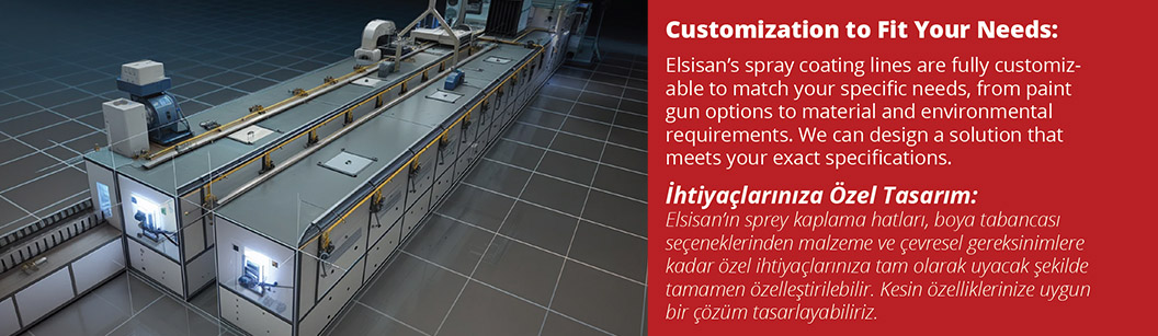
Customization and Additional Sections

As mentioned above, these are the main sections of most spray coating lines in the industry. However, more than one spray coating booth and curing areas may need to be added to the line to achieve certain effects or to work with different kinds of paint chemicals. When you contact our engineering team, we will guide you through your decisions, providing necessary advice to create efficient, long-lasting line operation details and help you choose the best investment strategy based on your parts, capacity, and other technical specifications.

Spray coating lines for glass - customization to fit your needs custom made painting lines

Elsisan’s Comprehensive Services

  • Engineering
    Our engineering approach combines 3D visualization with expert analysis to identify challenges early and enhance efficiency, ensuring projects are effective from inception and adaptable to specific needs and environments.
  • Production and Installation
    tilizing cutting-edge technology, we uphold high production standards. Transparent workflows keep clients informed, while modular designs and strategic installation methods ensure rapid, seamless integration into client operations.
  • Training
    Our training programs are designed to empower clients, enabling optimal utilization of our systems. Through these programs, clients gain the necessary skills and knowledge for sustained success and maximum benefit from our solutions.
  • Service
    Our dedication to clients extends beyond project completion. We offer global service and expert guidance. Using network connectivity, we remotely access machines for support, ensuring solution effectiveness and high client satisfaction.

Conclusion

At Elsisan, our motto is “From Concept to Completion: Engineering Your Success.” We guide you along the way, providing necessary training and service even after the painting line is delivered. As a turnkey manufacturer of coating lines, we develop long-lasting relationships with our customers to be their global provider and partner in glass spray coating applications.

To learn more and get an offer, reach out to the Elsisan Team today through the email address and contact information below. We will be happy to assist you and provide our globally renowned lines to create the best investment strategy for your company.

Web : elsisan.com
E-Mail : elsisan@elsisan.com

Industrial Glass Painting Technologies

Industrial Glass Painting Technologies

 In the glass industry, which is gaining momentum today, serial painting of bottles and glasses is done by fully automatic machines. Products such as glass bottles, glasses, souvenirs, glassware are painted with two types of paint, organic and inorganic. Organic paints are water-based or solvent-based double components. Paint application; can be made by air injection, roll printing and silk screen print methods. Organic paints can be dry by air drying, oven drying and UV drying. After drying, the paint forms a hard film.

Inorganic paints are water-based or solvent-based, single component. Matte coating process can also be applied as frosting. The glass is mattified with the matting frosting application and a frosted appearance is provided on the surface. Paint application; can be made by air spray, roll printing and silk screen print methods. Inorganic paints are dried at ovening temperatures starting from 550°C. The paint becomes a complete whole with the glass after ovening process.
 

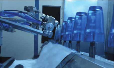
Glass components moving past automatic spray guns on a conveyor

Air Spray Paint Application

Glass products to be painted are loaded from the loading area to the conveyor flowing at the adjusted speed by the operator or the robot. The glass first goes through the flaming process to abrade its surface. In the flaming process, the glass surface is exposed to thermal oxidation for less than one second with the flame formed by using gases such as methane, propane, butane. With the flaming process, the ability of the paint to adhere to the surface is increased. In the continuation of the coating process, the product passes in front of the antistatic cleaning unit in order to remove the static tension on the surface. The surface is statically cleaned and ready for paint.

Painting can be done with a conventional air gun, bell gun or disc system in accordance with the capacity and the shape of the glass piece. With conventional air guns, many different colors can be applied at the same time in cases where quality expectations are not high.

Thus, the inventory cost is reduced and the packaging time is shortened. In mass productions with high capacity, thanks to the 80-90% transfer efficiency with the Bell gun and disc system, despite the increase in paint prices, economy in paint consumption is ensured. Bell and Disk systems provide excellent paint uniformity and quality. Extremely low overspray reduces cabin exhaust flow and reduces cleaning requirements.

Cabin where paint applications are made; It can be produced in two different types with water screen or dry filter. Today, dry filter technology has progressed positively and has become more preferred.
 

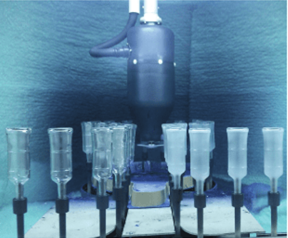
Glass bottles positioned beneath an automatic spray applicator

Paint application is made in a positive pressure room. With the help of positive pressure booth, the paint application is isolated from the external environment and dust entry into the cabin is prevented. In all painting systems, the glass is rotated around its axis during painting. Paint-applied products enter the flash-off section. Resting before the oven is done by staying in the flashoff for about 10 minutes.

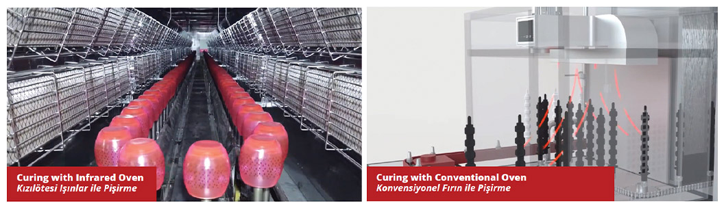
Paint drying oven can be made with conventional or infrared. In infrared ovens, the oven time is shortened by 1/3. For example, the curing time, which is 20-25 minutes in conventional conventional ovens, decreases to 6-8 minutes. Fans are used for heat distribution in conventional furnaces. With the fan circulation, dust flying in the fan also occurs. Since there is no air circulation in the infrared oven, the paint is cured in a dust-free environment.

Glass products coming out of the oven enter the cooling section and cool down to the touch temperature. Glass products after the cooling section; arrives at the unloading station. It is emptied and packaged by the operator or the robot or transferred to the high temperature furnace.
 

Blue glass containers passing spray guns on a conveyor

Glass Painting Technologies In Industry 4.0

Glass painting machines are machines suitable for the new industrial revolution defined as Digital Industry, 4th Industrial Revolution or Industry 4.0, with loading and unloading done by robots.

Conveyor and loading and unloading robots communicate and move synchronously through sensors communicating with each other in the glass painting machine. All of the glass painting machines are PLC and computer controlled. A separate recipe can be created for each product. Important values such as how many glass products are painted per hour, paint consumption, energy consumption, thermal energy consumption, stopping and working times can be recorded and reported. In addition, the user is warned with fault alarms and maintenance alarms depending on the anticipated maintenance period.
 

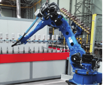
Industrial robot serving an automated glass painting line

With the help of remote access, PLC system can be intervened and data can be received from the office or from a different country. Fully automatic glass painting machines can work completely unmanned with its developing technology, thus providing speed, economy, efficiency and quality. With the increase in efficiency and quality, the global market share of glass products can be increased significantly.

To get an detailed information about industrial glass painting, please visit product page from the link below

https://elsisan.com/tr/endustriler/cam-sektoru

Canay IŞIKMAN

Project Engineer

Project Department

Elsisan A.Ş

Chemical Surface Preparation Process Before Paint Application

Surface preparation is one of the most important factors affecting the quality of the product after paint application.

Before the paint application process, it is the cleaning of grease, welding dirt and similar impurities on the surface of the material arising from the production by applying solvent, acidic and alkaline chemicals from the material surface.

The surface preparation process does not have a protective feature. It cleans the material and makes it suitable for the paint to adhere to the surface. Surface treatment is applied to increase the corrosion resistance of all paint coatings.

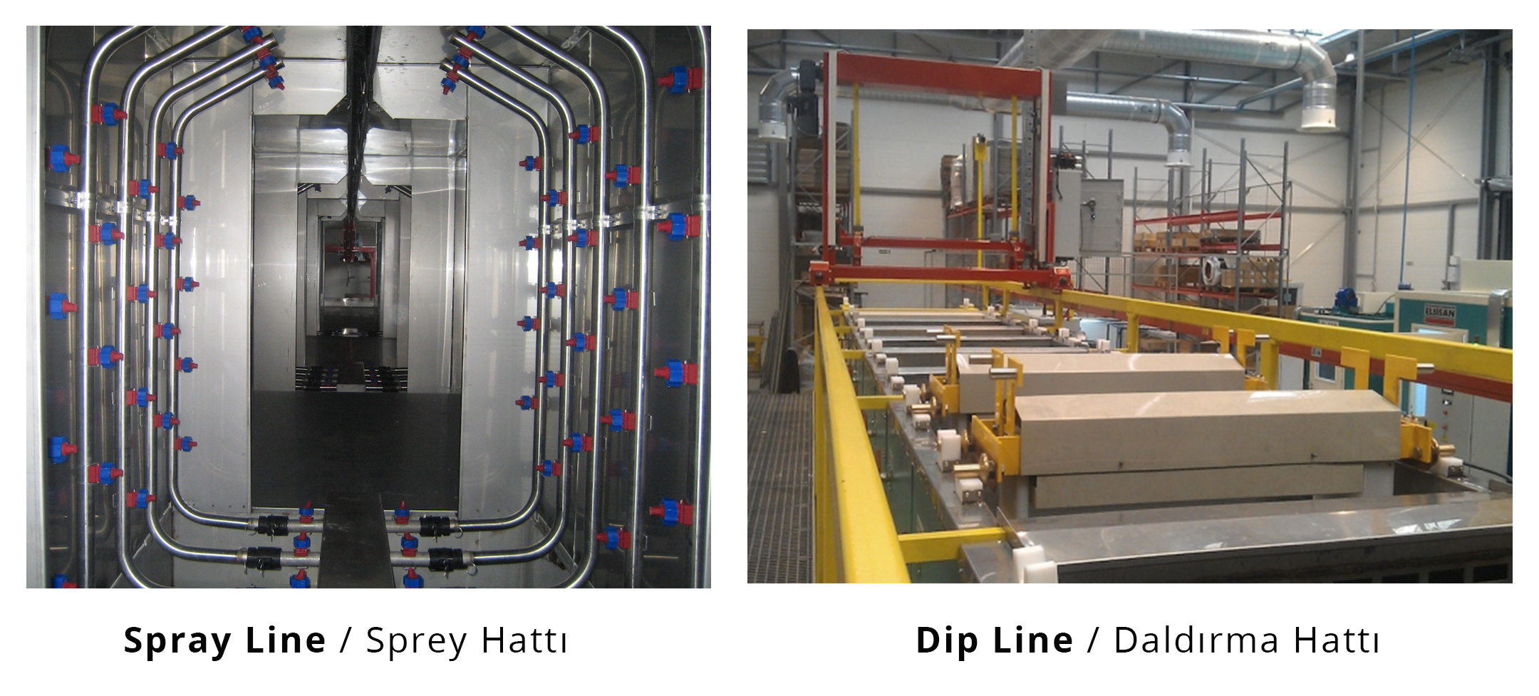
As a result of surface treatment, corrosion resistance and adhesion of paint to the surface increase. Corrosion and other problems in the coating may result from improper application of the surface treatment process. Surface treatment is usually more important than the final coating. Generally, two types of surface preparation methods are used. The surface preparation method can be selected according to material structure and capacity.
Generally, two types of surface preparation methods are used. The surface preparation method can be selected according to material structure and capacity.

  • Dipping type surface preparation
  • Spray type surface preparation

Dip line / Spray line

The factors that affect the surface preparation process sequence and selection are mainly,

  • Quality and type of metal
  • Condition of the surface: pollution rate and types of pollution that need to be cleaned from the surface
  • Finished product, using areas and the level of protection required
  • Economic and environmental factors.
The most basic chemical cleaning solutions, depending on the above factors,

  • Iron Phosphate
  • Zinc Phosphate
  • Nano Coating

A. Iron Phosphate
It is applied to surfaces that do not require high corrosion resistance. For this reason, it is preferred in the coating of products used in closed environments that will be exposed to less corrosion. Since the number of baths is less than the zinc phosphate coating, the operating and investment costs are lower. Spray pressure should be chosen between 1.5 – 2 bar in spray pre-treatment lines. Degreasing and iron phosphate baths are between 60°C ±5°C. The pH value of the iron phosphate bath should be monitored so that it remains between 5 ± 1. Values to be followed in the relevant process, temperature, pH, conductivity, pump pressure, nozzles and time.

Basically the process sequence,

  1. Degreasing
  2. Rinsing
  3. Iron Phosphate
  4. Rinsing
  5. Passivation
  6. DI Rinsing
  7. Drying oven

B. Zinc Phosphate

It is used on surfaces that require high corrosion resistance. It is a type of phosphating commonly used in the automotive, electronics and white goods industries. Spray pressure should be chosen between 1.5 – 2 bar in spray washing lines. The degreasing baths should be at 60°C ±5°C and the zinc phosphate bath at 50°C ±5°C. The values to be followed in the relevant process are temperature, pH, conductivity, pump pressure, nozzles and time.

Basically process sequencing:

  1. Degreasing
  2. Degreasing
  3. Rinsing
  4. Activation
  5. Zinc Phosphate
  6. Rinsing
  7. Passivation
  8. DI Rinsing
  9. Drying Oven

C. Bonderite (Nano Coating)

There is almost no waste compared to phosphate coating applications. While water usage is reduced in this type of coating, it reduces the COD and BOD load to zero as it does not contain heavy metals. Since there is no need for heating as in zinc and iron phosphate baths, energy costs are significantly reduced. Cleaning time and maintenance costs are also reduced as there is no clogging in nozzles, filters and heat exchangers as there is no waste. Nano coating process time is shorter than phosphate coatings. In corrosion tests, it is seen that iron phosphate and zinc phosphate provide corrosion resistance.

The values to be followed in the relevant process are temperature, pH, conductivity, pump pressure, nozzles and time.

Basically process sequencing:

  1. Degreasing
  2. Rinsing
  3. DI Rinsing
  4. Nano Coating
  5. Rinsing
  6. DI Rinsing
  7. Drying Oven

Degreasing Types

1. Degreasing

All metal parts contain grease on their surface. The purpose of the grease on the metal part’s surface is to protect it from corrosion until the parts come to the process phase. The degreasing process is generally implement in the first phase of pre-treatment. The degreased part becomes ready for rust removal and phosphate application. Applying these processes to the metal with a greasy surface does not give healthy results, and the main problem arises after the paint is made. Color differences can cause yellowing and lightening of the paint. The degreasing process can be done alkaline, acidic or neutral. The type of metal, the way of application, the type of grease determine the properties of the chemical to be used. In a correct degreasing, it is desirable to have the properties of heating the surface, penetrating deep, removing the grease, breaking the grease, emulsifying and rinsing easily. Degreasing chemicals are used by dipping, spraying and wiping methods. The degreasing process is carried out by saponification of vegetable or animal oils and emulsification of mineral oils. It is also important that the metal does not darken and does not wear heavily in degreasing baths.

Bath control parameters to be considered are:

  • Temperature
  • Concentration
  • Total Alkalinity
  • Time

a. Alkaline Degreasing

The alkaline degreasing process is carried out in hot and alkaline baths. Alkaline degreasing chemicals are used in concentrations such as 1 – 15%. This change in concentration varies due to the difference in the amount of grease as well as the design of the line as dipping or spraying. The pressure effect in the spray baths will minimize the chemical percentage. Density in the amount of grease will increase the chemical ratio. The pH of the bath is monitored between 10 – 13. Temperature is the most important parameter to be followed in alkaline degreasing. The operating temperature varies between 50-95°C. The action that can be taken at low temperatures is to extend the time by increasing the concentration. The degreasing of the materials entering the degreasing bath can be taken between 5 and 20 minutes.

b. Acidic Degreasing

The Acidic Degreasing process is generally used for parts with rust on the metal surface. As grease is removed from the metal surface, rust is also cleaned. This type of degreasing works in an acidic environment. It certainly contains acids, (phosphoric, hydrochloric, sulfuric etc.) wetting agents and sometimes inhibitors. The pH of the Acidic Degreasing bath is between 1 and 2. Although the bath temperature can be used at ambient temperature, using it at high temperatures will increase the degreasing capacity and the reaction rate. Chemical concentration can be used between 5 – 50%. Metal surfaces with deep rust are cleaned in high concentration baths. Bathroom material must be made of stainless or plastic material with high acid resistance. In addition, after the acidic degreasing bath, the metal surface becomes susceptible to corrosion. For this reason, the part must be taken to the next process bath immediately.

c. Neutral Degreasing

Neutral Degreasing chemicals are generally used in spray surface treatment lines. It is also used as a degreasing agent in iron phosphate baths. Since the pH range is 6 – 8, its effect is very less compared to acidic and alkaline degreasing. The most common use is in the form of degreasing in iron phosphate lines. Generally, spray iron phosphate chemicals contain degreasers, but when the bath concentration begins to decrease, neutral degreasing agents are added. It is preferred because it is used in low concentrations such as 1-2%, as well as being treated with iron phosphate in the same bath. Working at temperatures between 50 – 55°C also provides a separate advantage.

Naim UZEL

Project Engineer

Project Department

Elsisan A.Ş

OBM-V Automatic Wet Paint Systems with Vertical Spindles

Small sized metal, plastic or glass products with a large number of production in many sectors such as automotive, glass, white goods, aerospace, furniture, construction, defense industry; OBM-V automatic wet paint machines with vertical spindles can be used for coating with wet paint for both corrosion and aesthetic purposes
(more…)

Rubber to Metal Bonding Agent Application Techniques and Solutions

As Elsisan, we offer many different options for our customers’ needs in our rubber metal bonding agent applications.(Rubber to metal bonding agents also known with different products names such as Chemosil, Chemlok, Megum) Some of our application solutions for these bonding agents are manual while some solutions are completely automatic application systems.

In order to offer the most suitable and economical solution to our customers, firstly the answers for following questions needs to be provided:

THINGS TO KNOW BEFORE STARTING:

  1. Dimensions of the parts and application areas: 
    Whether the part has a surface that will not be painted or has a surface to be masked is important when proposing a solution. In addition, the application of what we call 2-dimensional parts, that is, parts with little or no depth, includes different application methods compared to the 3-dimensional parts whose all surfaces will be painted.
    For 2-dimensional parts (with little or no depth), generally belt conveyed (horizontal type) application solutions are offered, while for 3-dimensional parts, solutions with ground or overhead conveyors are preferred. Other than those two solutions, when it is requested to apply agent to all inner and outer surfaces of the parts, dipping type solutions are offered. In this solution the application can be made by dipping the suspended parts into tanks.

  2. Capacity:
    Capacity is critical in understanding whether you need manual system, semi-automatic or automatic system solutions. At this point, making the right choice will significantly affect the investment and operating costs of the customer.

  3. Factory installation area and part loading-unloading methods:
    Depending on the area to be installed in the factories, more compact designs can be preferred in automatic application solutions.
    The part loading and unloading area plays an important role in the designs we offer to our customers. While in some companies, our customers prefer solutions that a single person can do loading and unloading from only one area. Some of our customers demand larger areas and sometimes lift-assisted loading solutions for loading heavy and large parts. At the same time, automatic loading and unloading solutions can be integrated into the design according to the demands of our customers, thus allowing spontaneous transition between different lines.

MODEL TYPES:

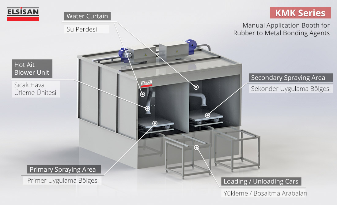
Manual Solution- KMK Series:

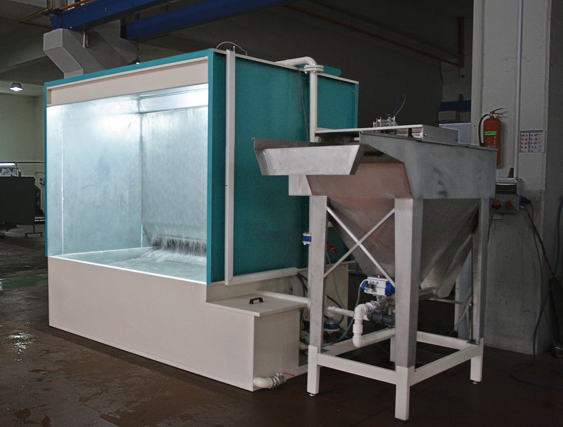
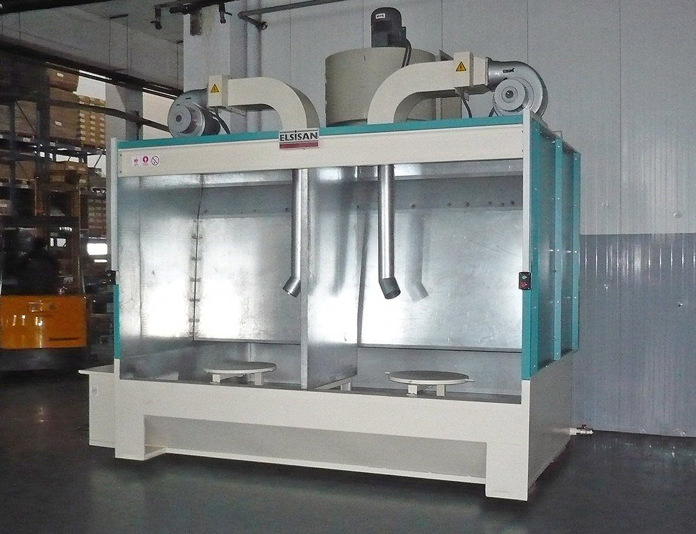
Manual rubber to metal bonding agent application solutions are done with water curtain spray booths. The application is done manually with a gun application by the operator. Overspray molecules are caught and accumulated in water by means of water curtains and nozzles. Other paint particles that are not caught by the water curtain are caught by separators in the suction section, thus preventing them from reaching the fan and being thrown out.

There is a tray in the cabinet to place the parts. The table is rotated manually by the operator. With the help of the hot air blowing pipes on the application area, the drying process is accelerated.

Visit KMK product page by clicking here

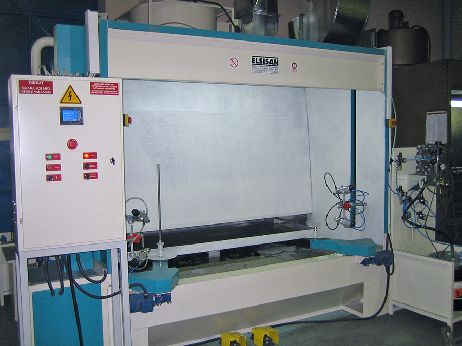
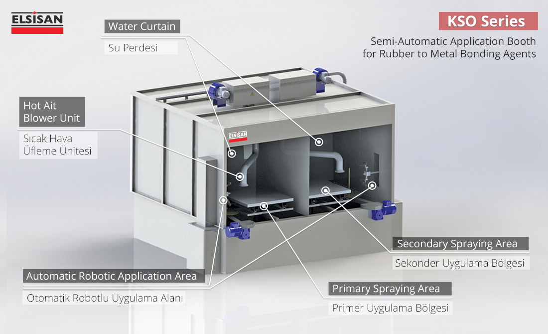
Semi Automatic Solution – KSO Series:

Compared to the manual solution, a 2-axis automatic application gun is used in this semi-automatic model. The table on which the parts are placed is also automatically rotated. The water curtain functions similarly to manual cabin to capture overspray particles. Other paint particles that are not caught by the water curtain are caught by separators in the suction section, thus preventing them from reaching the fan and being thrown out. With the help of the hot air blowing pipes on the application area, the drying process is accelerated.

Visit KSO product page by clicking here

Fully Automatic Application Solution with Belt ConveyorOKM-H Series:

OKM-H series are used to apply rubber to metal bonding agent to 2-dimensional parts, that is, parts with no or less depth. The parts are placed on the tray and loaded on the horizontal conveyor. With the help of horizontally moving conveyor system, the parts are moved through preheating, primary application, drying, secondary application and cooking processes. Then parts are brought to the unloading area in a cooled state which are unloaded by the operator. The entire system can be instantly monitored and controlled from the control panel.

Visit OKM-H product page by clicking here

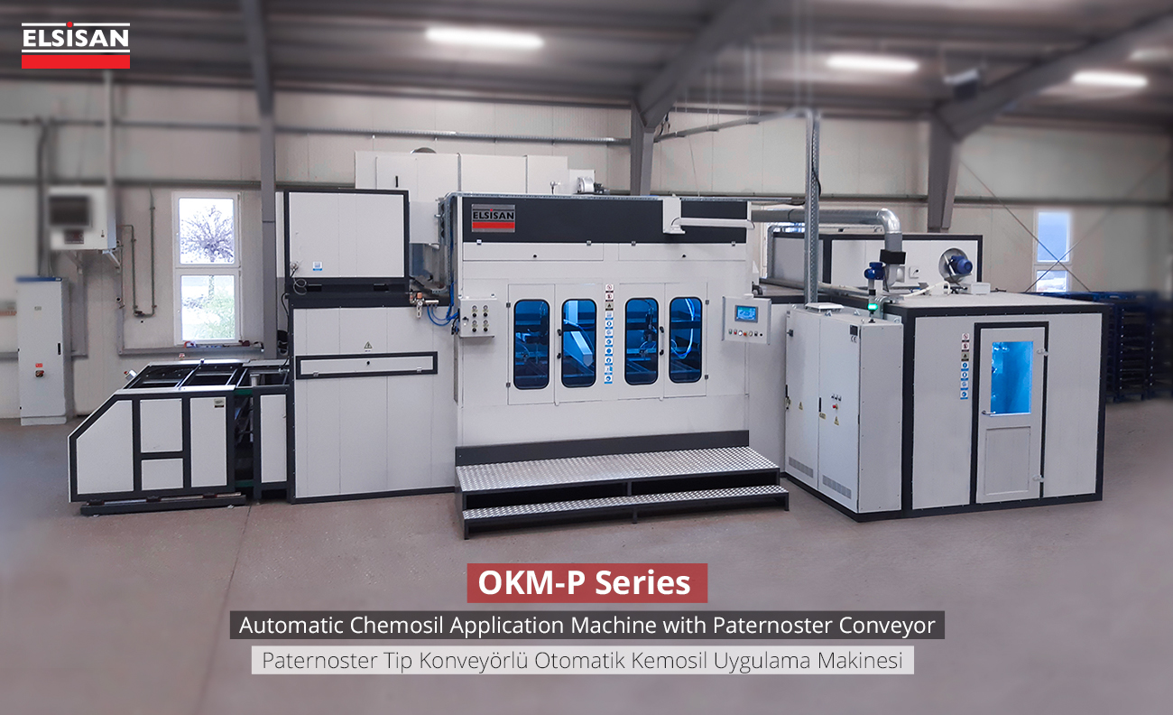
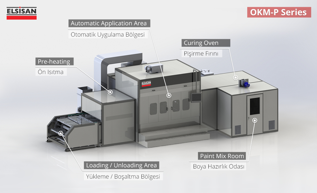
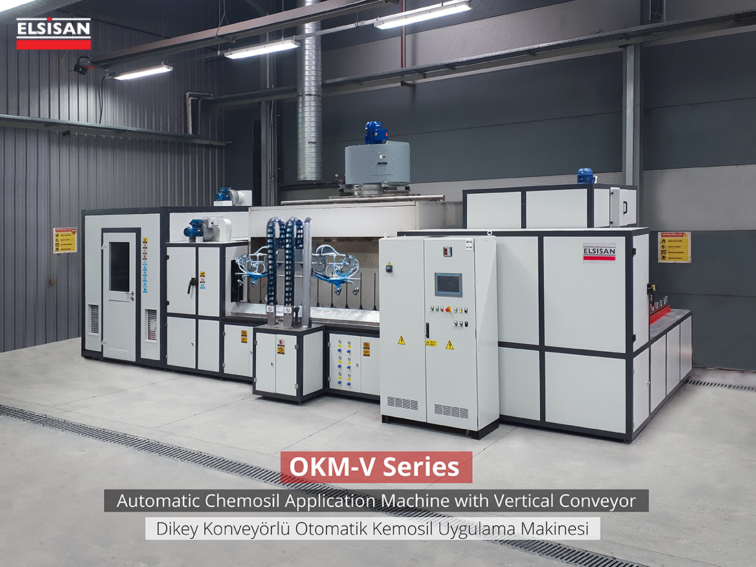
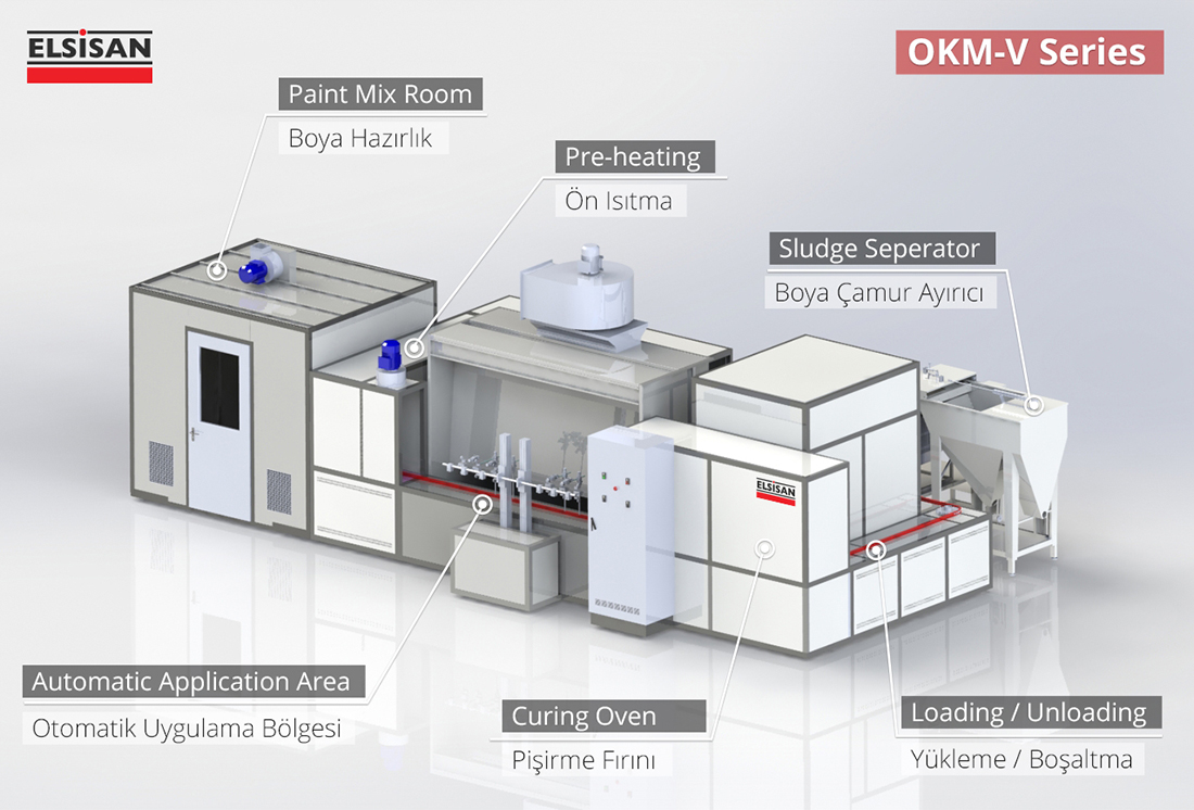
Fully Automatic Application Solution with Paternoster Type ConveyorOKM-P Series:

The most important difference of the OKM-P model, which is very similar to the horizontal belt application(OKM-H Series), is that the unloading and loading points of the trays are made from the same area. In this way, the operator can load and unload from one side. At the same time, the fact that the baking process continues when the trays descend to the lower section of the conveyor, makes the machine more compact and allows the machine to occupy a smaller area in the factory. The application process is done as follows: The parts are placed on the tray and loaded on the horizontal conveyor. With the help of horizontally moving conveyor system, the parts are moved through preheating, primary application, drying, secondary application and cooking processes. Then parts are brought to the unloading area in a cooled state which are unloaded by the operator. The entire system can be instantly monitored and controlled from the control panel.

Visit OKM-P product page by clicking here

Fully Automatic Application Solution with Floor ConveyorOKM-V Series:

The most important reason for choosing this model compared to our horizontal band models is that all surfaces of the parts will be circumferentially sprayed. Parts can be loaded into conveyor in two different ways. First solution is used for cylindrical parts, which are vertically loaded on top of each other while the second solution is used for parts with wider surface areas, which are loaded in circular fashion. Optionally, an internal paint gun can be added to paint inner surfaces of the parts.

Step by step moving conveyor takes parts through preheating, primary application, drying, secondary application and cooking processes. Then parts are brought to the unloading area in a cooled state which are unloaded by the operator. When the parts come in front of the application area, the parts are rotated, thus ensuring a homogeneous application. The entire system can be instantly monitored and controlled from the control panel.

Visit OKM-V product page by clicking here

Fully Automatic Application Solution with Dipping OKM-D Series:

The dipping type application machine is designed for the parts that require bonding agent to be coated on the entire surface of parts. Firstly the parts are hanged on to the overhead conveyor from the loading area. Then parts go through preheating oven, primary coating tank,  dripping area, drying oven, secondary coating tank, curing oven and unloading area. The entire system can be instantly monitored and controlled from the control panel.

Visit OKM-D product page by clicking here

Fully Automatic Application Solution with Rotary Coating Pan BKM Series:

Rotary coating pans are ideal solution for small sized parts and parts that requires all their surfaces to be painted. The parts loaded into the pans, then parts are turned over by rotation and metal rubber bonding is applied to parts. Drying is done between the application processes and finally the application is completed. The entire system can be instantly monitored and controlled from the control panel.

Visit BKM product page by clicking here

Sludge Seperator Systems- BCA Series:

We recommend using Sludge Separator Systems to accelerate the operation and maintenance processes to our customer which use rubber to metal bonding applications. Sludge Separator systems can be connected to all water-based spray booths. Separator system automatically separates the paint sludge and keep the water used in the booth clean while minimizing maintenance costs. It also increases the application quality.

How Sludge Separator System works:

Sludge Separator Unit is connected to the Paint Machine with a pump. With the help of the pump, the paint-water mixture is transferred to separator system and dosed with the chemicals. The sludge in the paint-water mixture is floated on the water surface with the help of chemicals. Then the floating paint waste is accumulated and separated with the help of the pneumatically operated clamps. The water purified from paint particles in the existing Paint Sludge Separator Machine is sent back to the Paint Machine by gravity.

Visit BCA product page by clicking here

Reach Us For More Details and Offer Requests:

As Elsisan we have provided our rubber to metal bonding applications globally over the years. With the help of our global experiences we know how important it is for our customers to have the right solution and a machine they can rely on for many years.

For your requests, you can reach us via our website or by email at elsisan@elsisan.com .

Below you can find our customer references which we have provided our metal rubber bonding agent application solutions:

The Importance of Using Ex-Proof Products in Liquid Painting Plants

Before discussing the importance of using ex-proof products in wet paint plants, it is useful to explain what the words ex-proof and ATEX mean:
(more…)

Filtration Types in Spray Booths

Read this article to learn more about filtration types in spray booths
(more…)

Contact Us